Breast cup

a technology of a cup and a cup body, which is applied in the field of a cup and a cup, to achieve the effect of minimum pumping duration and maximum pumping performan

Active Publication Date: 2019-08-08
MEDELA HLDG AG
View PDF1 Cites 11 Cited by
  • Summary
  • Abstract
  • Description
  • Claims
  • Application Information

AI Technical Summary

Benefits of technology

[0016]Therefore, it is an object of the invention to create an alternative method for operating a breastpump unit and also an alternative breast shield, which allow a maximum pumping performance and also a minimum pumping duration per pumping session.

Problems solved by technology

Although those relatively recent breast shields show solution attempts that are good in part in order to approach natural suckling, optimal imitation of the nature and thus the optimal shape and pressurization of a breast shield have not yet been found.

Method used


Image

  • Breast cup
  • Breast cup
  • Breast cup

Examples


first embodiment

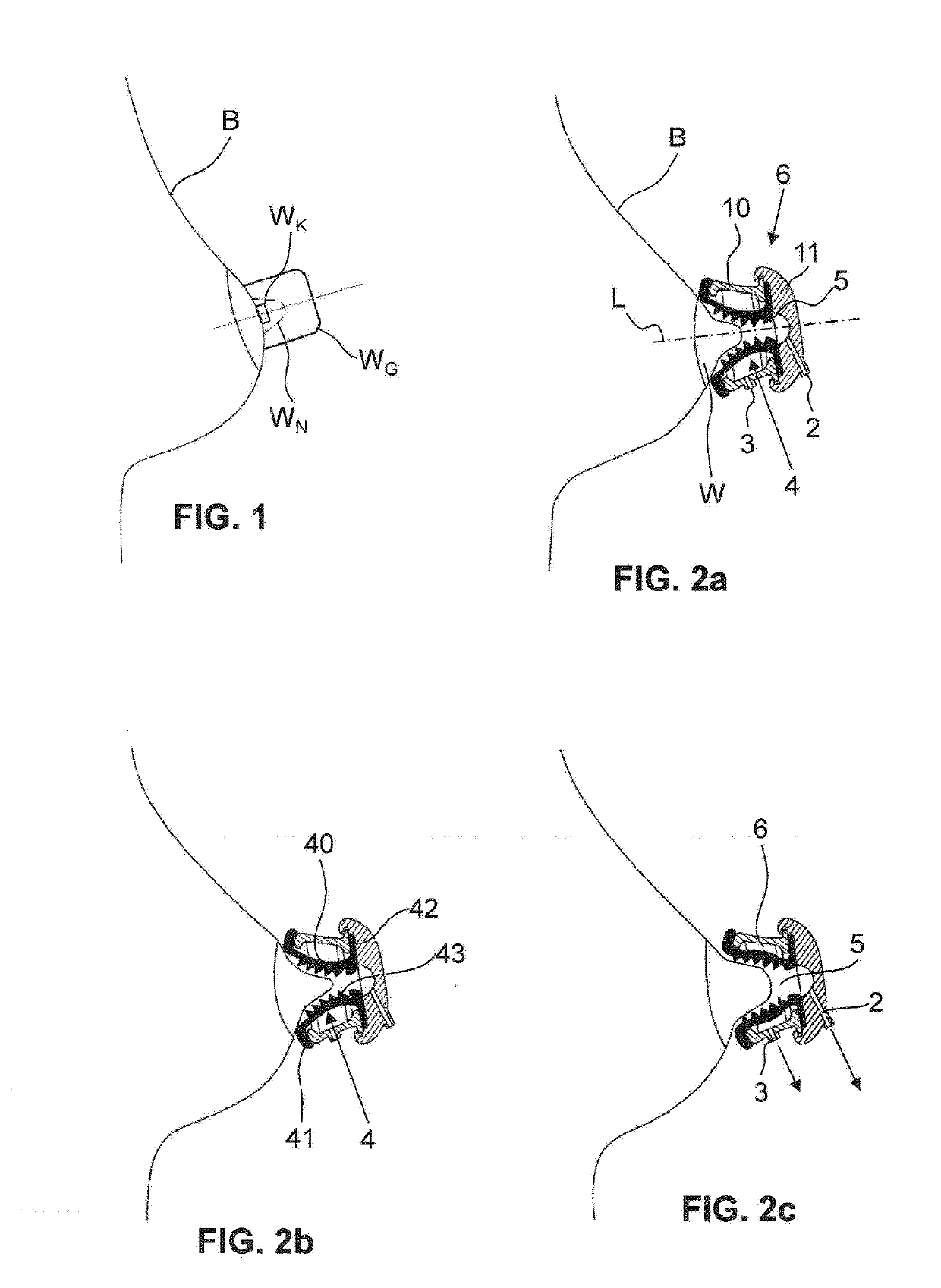
[0099]FIGS. 2a to 2c illustrate a breast shield according to the invention. It has a rigid or semirigid breast shield body 1 which is produced preferably from plastics material. In this example, the breast shield body 1 is designed in two parts. It has a base 10 and a cover 11.

[0100]The cover 11 has a first vacuum connection 2 for connecting to a vacuum pump. The vacuum pump has at least one vacuum unit for generating a negative pressure. The vacuum pump is illustrated in FIG. 13 and is described later on in this text.

[0101]The base 10 is formed in a substantially frustoconical manner in this example. It can also have some other shape; for example, it can be configured in a hollow-cylindrical manner. In this example, it has a breast-side fastening flange and a pump-side fastening flange. Provided on the base 10 is a second vacuum connection 3 which allows a connection to preferably one and the same pumping unit or to another pumping unit of the vacuum pump.

[0102]The base 10 and the ...

second embodiment

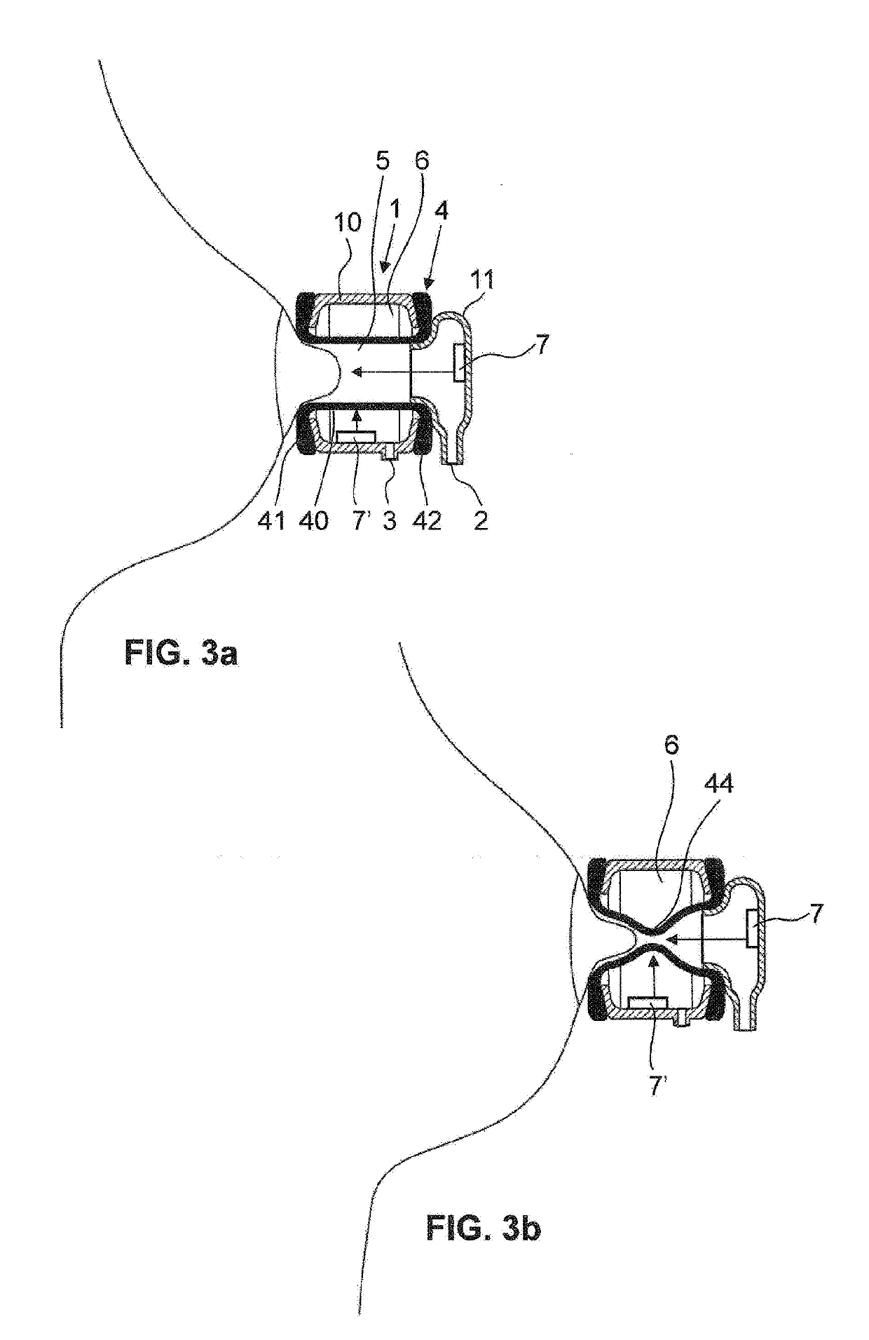
[0117]FIGS. 3a and 3b illustrate a breast shield according to the invention. The basic structure of the breast shield is the same as in the first exemplary embodiment and therefore will not be explained in more detail here. The rigid or semirigid breast shield body 1, in which the flexible inner part 4 is arranged, is once again present. The first vacuum connection leads into the inner chamber 5 and the second vacuum connection 3 leads into the outer chamber 6. The outer chamber 6 encircles the outer side of the flexible inner part 4. The inner wall of the main body 40 is configured in a smooth manner in this illustration. In other variants, it is likewise provided with retaining elements 43, for example with ribs. A constant negative pressure is again preferably applied in the inner chamber 5 and a pulsating negative pressure that exceeds the latter in terms of magnitude is present in the outer chamber 6. In other words, here too, the method according to the invention can be applie...

third embodiment

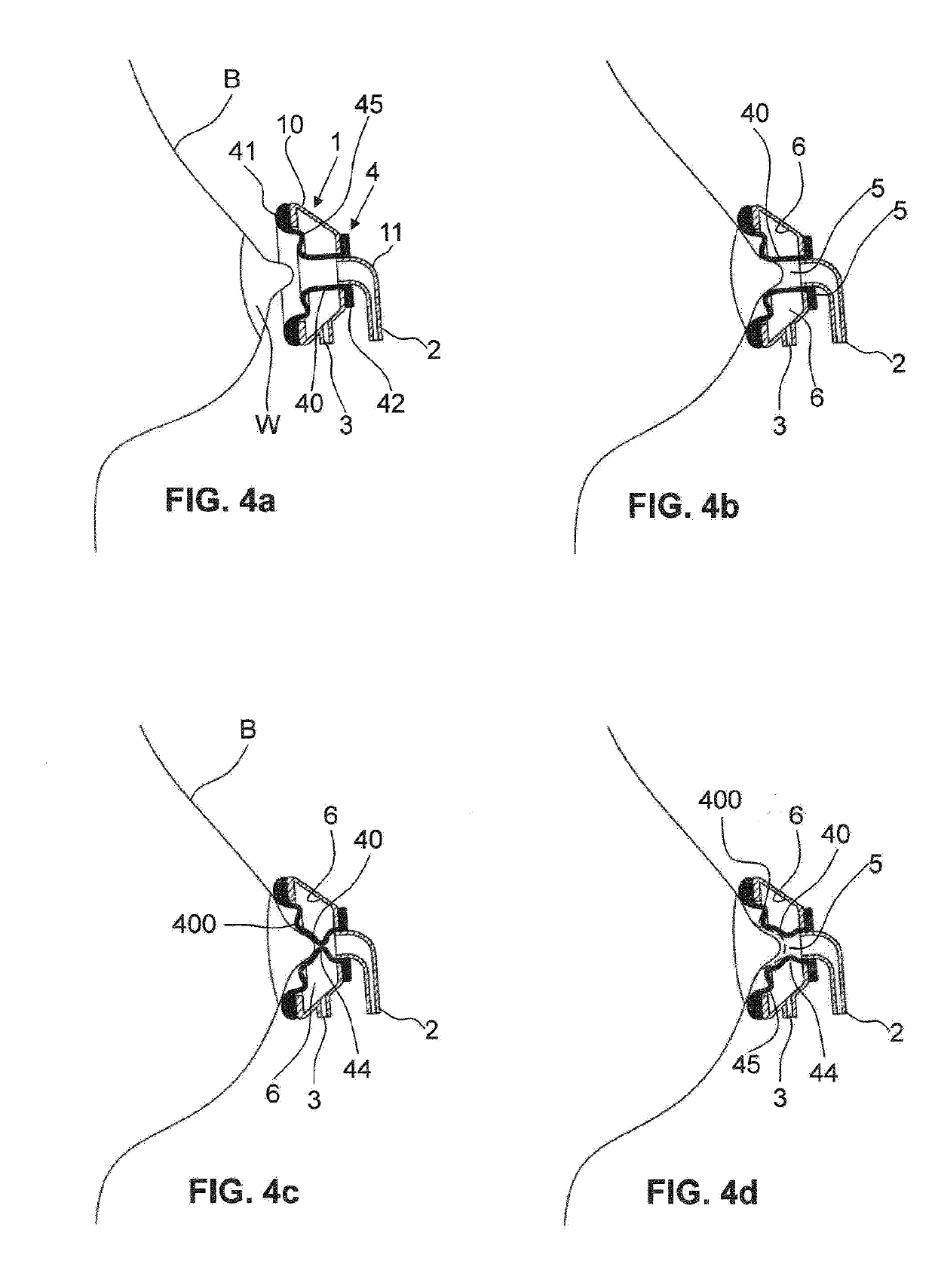
[0123]FIGS. 4a to 4d illustrate the breast shield according to the invention. The breast shield body 1 is configured here in one piece and again has the two connections 2 and 3 and the inner chamber 5 and the outer chamber 6. The flexible inner part 4 has been fitted over the two end faces of the breast shield body 1 and held in this way. The main body 40 of the flexible inner part is configured in a substantially hollow-cylindrical manner, wherein it transitions at its breast-side end into an outwardly directed, encircling and self-contained arch 400. This arch 400 can have the same wall thickness as the cylindrical part of the main body 40. However, it can also be embodied in a thickened manner. The main body 40 can have been produced in a multicomponent injection-molding process, in particular in a two-component injection-molding process.

[0124]The encircling breast-side flange of the flexible inner part 4 is directed outward and in turn forms the encircling, self-contained applic...


PUM


Abstract

A method for operating a breastpump unit for expression of human breastmilk and various breast shields for use in this method allow a maximum pumping performance and a minimum pumping duration per pumping session. The breast shield has an inner chamber for receiving a nipple of the breast and also at least one outer chamber which at least partially surrounds the nipple. The inner chamber is subjected to a constant pressure and the at least one outer chamber is subjected to a pulsating pressure.

Description

CROSS-REFERENCE TO RELATED APPLICATION[0001]The present application is the US national phase of International Application No. PCT / EP2016 / 070742, filed Sep. 2, 2016.TECHNICAL FIELD[0002]The present invention relates to a breast shield for expression of human breastmilk.PRIOR ART[0003]Manually operated and motor-driven breastpump units for expression of human breastmilk are known. They have a breast shield or two breast shields for sealing application to the breast. This at least one breast shield is connected to a manually operated or motor-driven breastpump directly or via a suction line. By means of the breastpump, a cyclically changing vacuum is generated which is transmitted to the breast shield in order to pump milk out of the breast.[0004]Breastpump units are intended to allow the breastmilk to be pumped out in a manner which is as close to the natural suckling of a baby as possible. In this case, special pumping sequences having a varying negative pressure and pumping frequenc...

Claims


Application Information

Patent Timeline
Patent Type & Authority Applications(United States)
IPC IPC(8): A61M1/06A61M1/00
CPCA61M1/064A61M1/0037A61M2205/0216A61M2205/13A61M2205/3306A61M1/06A61M1/066A61M1/75A61M1/067A61M1/0697A61M1/06935A61M2210/1007
Inventor LARSSON, MICHAELPFENNIGER, ERICHRIGERT, MARIOHONER, SEBASTIANVISCHER, PETERHARTMANN, PETER EDWIN
Owner MEDELA HLDG AG
Why Eureka
Try Eureka