Screw-type vacuum pump having overpressure openings

a vacuum pump and screw-type technology, which is applied to the components of rotary/oscillating piston pumps, machines/engines, liquid fuel engines, etc., can solve the problems of power loss and strong increase in the energy consumption of screw-type vacuum pumps, and achieve the effect of increasing the effective cross section of the entire overpressure opening

Active Publication Date: 2013-12-10
LEYBOLD HERAEUS GMBH & CO KG
View PDF8 Cites 0 Cited by
  • Summary
  • Abstract
  • Description
  • Claims
  • Application Information

AI Technical Summary

Benefits of technology

[0007]According to the disclosure a plurality of overpressure openings are provided which are preferably arranged on the same pressure level. By providing a plurality of overpressure openings, the effective cross section of the entire overpressure opening can be increased in a simple manner in order to guarantee for a fast medium removal.
[0014]Suitable materials for the valve body and the valve seat are, in particular, material pairings of elastomer and metal. For instance, an elastomer ball may be arranged in a valve seat made from a metallic material, or a metal ball may be arranged in a valve seat made from an elastomer material. It is further possible to provide elastomer-coated metal balls which would be arranged in a metal valve seat. Moreover, combinations of hard and soft metal materials or ceramic materials are possible. A suitably selected material pairing can guarantee a good sealing in the closed state of the overpressure valve. Further, the selection of a material is done on the basis of the process medium to convey and of the temperatures prevailing as well as the required weight for weight-loaded valves.
[0016]In another preferred embodiment, the channel of the overpressure outlet is closed with a housing cover. Possibly, a plurality of channels provided, which are specifically integrated in the pump housing, can be closed with a common cover. Here, the housing cover is preferably designed such that it extends over the entire length of the channel so that the housing cover forms or closes a longitudinal side of the channel. Thereby, it is becomes possible in a simple manner to clean and maintain the channel or channels of the overpressure outlet as well as the valves preferably arranged therein. Further, when assembling the screw vacuum pump, it is readily possible, with the housing cover removed, to provide the corresponding valve bores at the position desired for the corresponding pump, since the channel is open to one side and is thus well accessible. Further, mounting the holding elements for the valve bodies and mounting the other components in the valve is thus facilitated.
[0018]In another preferred embodiment, the at least one channel of the overpressure outlet extends over the entire length of the screw vacuum pump, i.e. from the pump inlet to the pimp outlet. Here, an overpressure valve is also provided in the inlet region. This is advantageous in that, if the desired pressure already prevails at the pump inlet, the medium can be carried off immediately through the channel, whereby unnecessary power consumption of the screw vacuum pump is avoided. If, for instance, the medium is pumped against atmosphere by two series-connected pumps and atmospheric pressure already prevails at the inlet of the second pump, the corresponding overpressure valve opens, so that, at the pump inlet of the second pump, the medium flows at least partially directly into the channel of the overpressure outlet.
[0020]For a positional definition of the valve bodies it is advantageous, specifically for weight-loaded valve bodies, to provide holding elements which in a particularly preferred embodiment are arranged within the channel. In this context, it is preferred to provide pin-shaped holders, wherein a spherical valve body is held by preferably three or four correspondingly arranged pins. This has the particular advantage that the holder for the valve body can be designed in a simple manner. For instance, it is possible to provide the same housing with one or a plurality of longitudinally extending channels for different types of pumps and different applications. The position of the overpressure openings is then defined by subsequently forming corresponding bores. Likewise, the holding elements can also be set into the channel in a simple manner. It is thus possible to provide one pump housing for different types of pumps or different applications, in which the desired positions of the overpressure openings and the valves can be realized in a simple manner.
[0021]In another preferred embodiment of the disclosure, the width of the overpressure opening, seen in the longitudinal direction of the screw vacuum pump or in the conveying direction, is chosen such that it is smaller than or equal to the tooth width of the screw rotor. Preferably, this takes the position of the overpressure opening into account, since the tooth width of the screw vacuum rotor may vary in the longitudinal direction. The reduction of the maximum width of the overpressure opening in the longitudinal direction, as provided by the disclosure, reduces an overflowing over the tooth of the screw rotor in the area of the overpressure opening. Thus, the occurrence of return flows, i.e. the occurrence of flows against the conveying direction, is reduced so that the pumping performance is not or only slightly reduced by providing an overpressure opening. This is particularly relevant in the mode of operation in which the overpressure valve is closed and the maximum pumping performance of the screw vacuum pump is to be achieved. Here, the width of the overpressure opening in the longitudinal direction of the screw rotor is preferably smaller than or equal to 90%, in particular smaller than or equal to 80% of the tooth width in this area.

Problems solved by technology

Such an over-compression, i.e., in the case of a pumping against atmosphere, a pressure above atmospheric pressure, results in a strong increase in the energy consumption of the screw vacuum pump.
This leads to power losses, since an unnecessary compression, i.e. an over-compression, of the medium to be transported is performed.

Method used


Image

  • Screw-type vacuum pump having overpressure openings
  • Screw-type vacuum pump having overpressure openings
  • Screw-type vacuum pump having overpressure openings

Examples


Embodiment Construction

with reference to preferred embodiments and to the accompanying drawings.

[0024]In the Figures:

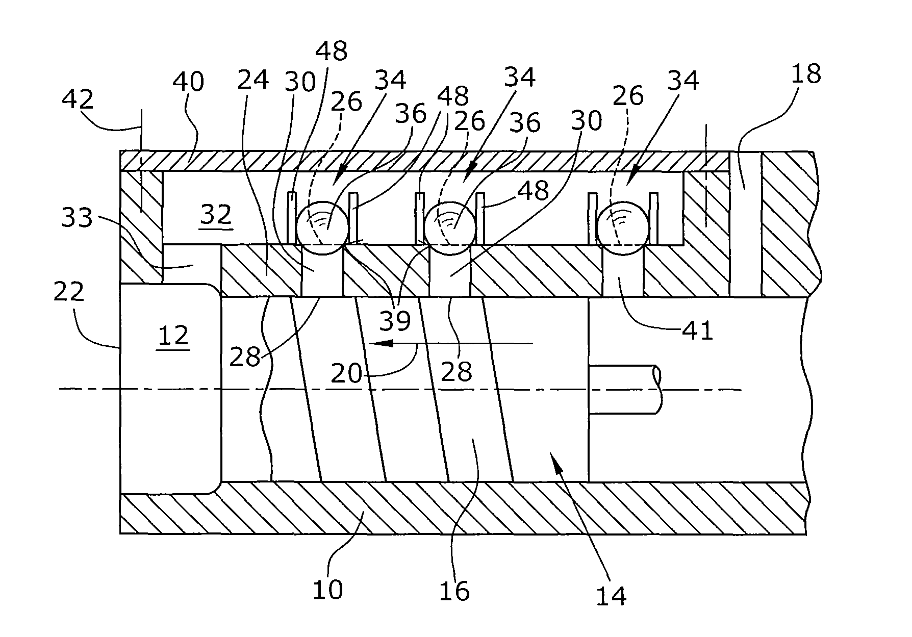
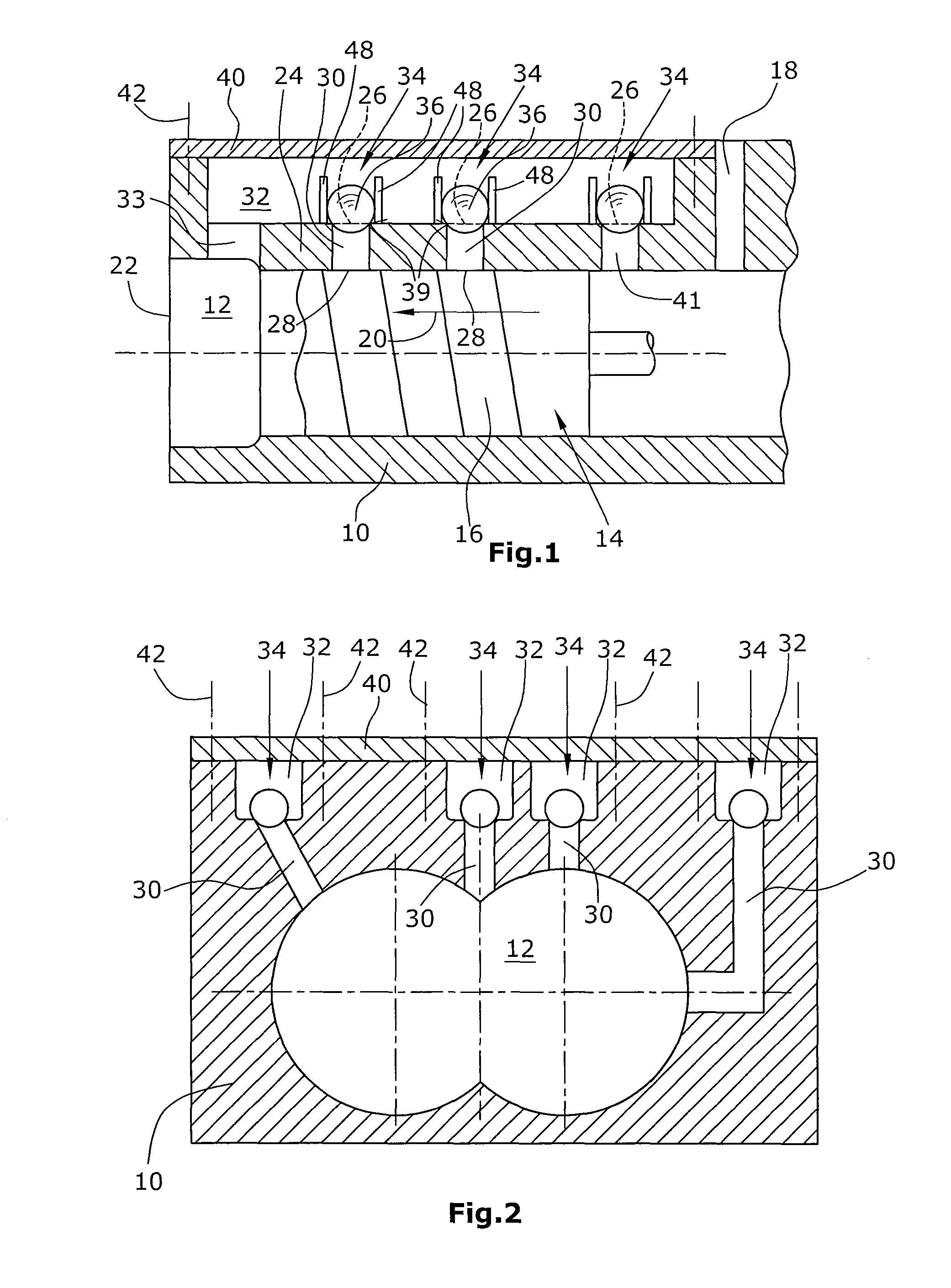
[0025]FIG. 1 is a schematic longitudinal section through a screw vacuum pump of a first embodiment,

[0026]FIG. 2 is a schematic transverse section through a screw vacuum pump of another preferred embodiment,

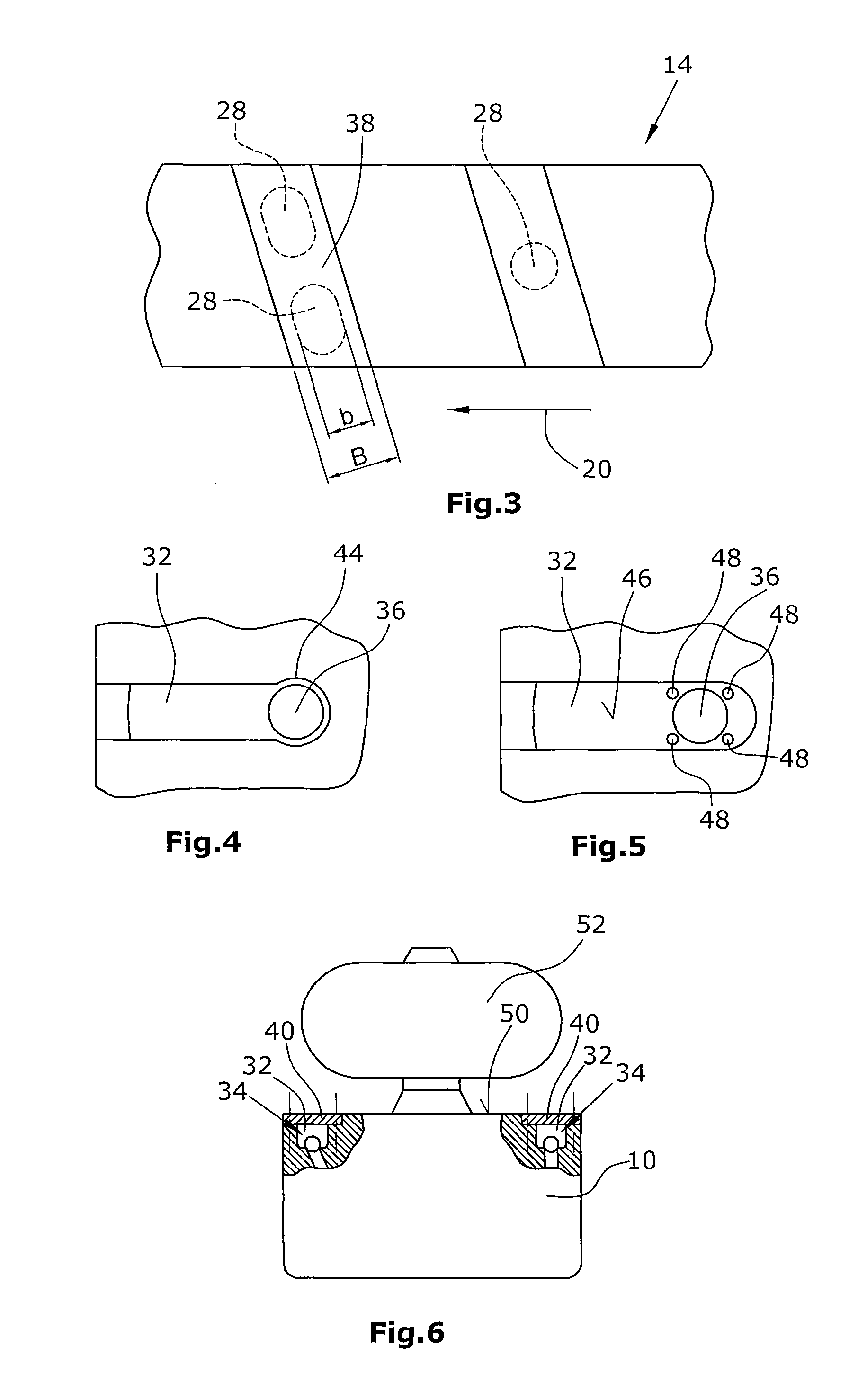
[0027]FIG. 3 is a schematic top plan view on a screw rotor with a plurality of overpressure openings indicated therein,

[0028]FIGS. 4, 5 are schematic illustrations of possible embodiments of overpressure outlet channels with overpressure valves arranged therein, and

[0029]FIG. 6 is a schematic side view of a screw vacuum pump according to the disclosure connected with a Roots pump.

DETAILED DESCRIPTION OF THE PREFERRED EMBODIMENT

[0030]According to a first embodiment (FIG. 1), a suction chamber is formed in a pump housing 10. Two screw rotors 14 are arranged therein one behind the other with respect to FIG. 1. The screw rotors each are provided with threads 16 on their outer sides so that th...


PUM


Abstract

A screw vacuum pump, in particular for compression against atmospheric pressure, comprises a pump housing defining a suction chamber. Two meshing screw rotors are arranged in the suction chamber. Further, an overpressure outlet provided, which comprises an overpressure opening in a side wall of the suction chamber. Further, an overpressure valve is arranged in the overpressure outlet. The width (b) of the overpressure opening in the longitudinal direction of the screw rotors is smaller than or equal to a tooth width (B) of the screw rotors.

Description

BACKGROUND[0001]1. Field of the Invention[0002]The disclosure refers to a screw vacuum pump, preferably for the compression of a medium, typically gas, with respect to atmosphere.[0003]2. Discussion of the Background Art[0004]Screw vacuum pumps have a suction chamber in a pump housing. Two screw rotors are arranged in the suction chamber. On their outer side, the screw rotors each have a helical thread, with the two threads of the screw rotors meshing in order to convey and compress the medium. Within the suction chamber, the medium conveyed is compressed from the suction side, i.e. the pump inlet, towards the pressure side, i.e. the pump outlet. Typical compression ratios of screw vacuum pumps are in the range from 1 to 106. Depending on the pressure present at the pump inlet, an over-compression can be caused in the screw vacuum pump. Such an over-compression, i.e., in the case of a pumping against atmosphere, a pressure above atmospheric pressure, results in a strong increase in ...

Claims


Application Information

Patent Timeline
Patent Type & Authority Patents(United States)
IPC IPC(8): F01C1/24F03C2/00F03C4/00
CPCF04C18/16F04C25/02F04C29/126F04C28/26F04C29/124F04C2250/10
Inventor BIRCH, PETERJENKINS, ROBERTMULLER, ROLANDJANICKI, MAGNUSGIEBMANNS, WOLFGANG
Owner LEYBOLD HERAEUS GMBH & CO KG
Why Eureka
Try Eureka