[0007]According to the disclosure a plurality of overpressure openings are provided which are preferably arranged on the same
pressure level. By providing a plurality of overpressure openings, the effective cross section of the entire overpressure opening can be increased in a simple manner in order to guarantee for a fast medium removal.
[0014]Suitable materials for the valve body and the
valve seat are, in particular, material pairings of
elastomer and
metal. For instance, an
elastomer ball may be arranged in a
valve seat made from a metallic material, or a
metal ball may be arranged in a
valve seat made from an
elastomer material. It is further possible to provide elastomer-coated
metal balls which would be arranged in a metal valve seat. Moreover, combinations of hard and
soft metal materials or
ceramic materials are possible. A suitably selected material
pairing can guarantee a good sealing in the
closed state of the overpressure valve. Further, the selection of a material is done on the basis of the process medium to convey and of the temperatures prevailing as well as the required weight for weight-loaded valves.
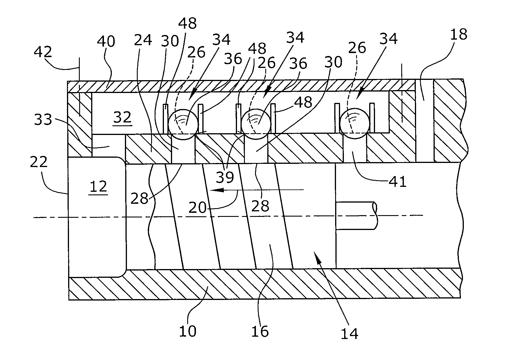
[0016]In another preferred embodiment, the channel of the overpressure outlet is closed with a housing cover. Possibly, a plurality of channels provided, which are specifically integrated in the pump housing, can be closed with a common cover. Here, the housing cover is preferably designed such that it extends over the entire length of the channel so that the housing cover forms or closes a longitudinal side of the channel. Thereby, it is becomes possible in a simple manner to clean and maintain the channel or channels of the overpressure outlet as well as the valves preferably arranged therein. Further, when assembling the screw vacuum pump, it is readily possible, with the housing cover removed, to provide the corresponding valve bores at the position desired for the corresponding pump, since the channel is open to one side and is thus well accessible. Further, mounting the holding elements for the valve bodies and mounting the other components in the valve is thus facilitated.
[0018]In another preferred embodiment, the at least one channel of the overpressure outlet extends over the entire length of the screw vacuum pump, i.e. from the pump inlet to the pimp outlet. Here, an overpressure valve is also provided in the inlet region. This is advantageous in that, if the desired pressure already prevails at the pump inlet, the medium can be carried off immediately through the channel, whereby unnecessary
power consumption of the screw vacuum pump is avoided. If, for instance, the medium is pumped against atmosphere by two series-connected pumps and atmospheric pressure already prevails at the inlet of the second pump, the corresponding overpressure valve opens, so that, at the pump inlet of the second pump, the medium flows at least partially directly into the channel of the overpressure outlet.
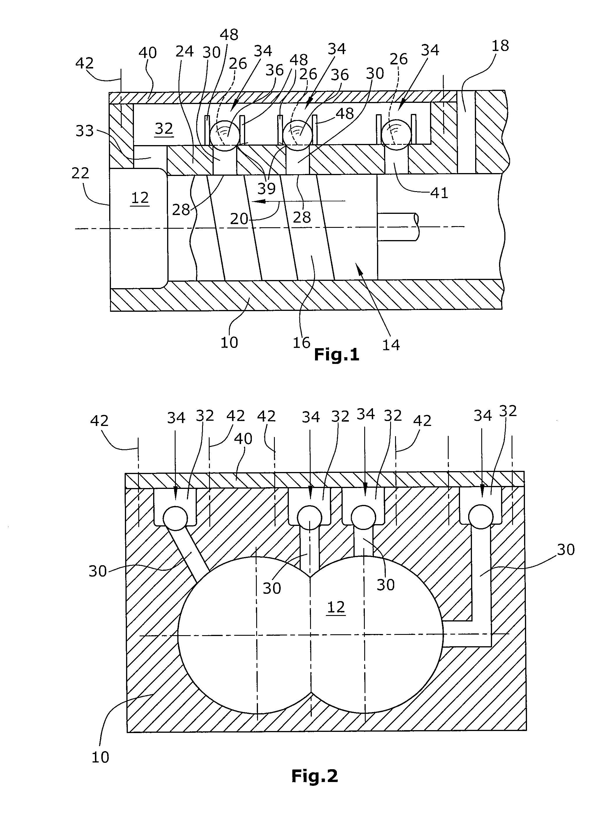
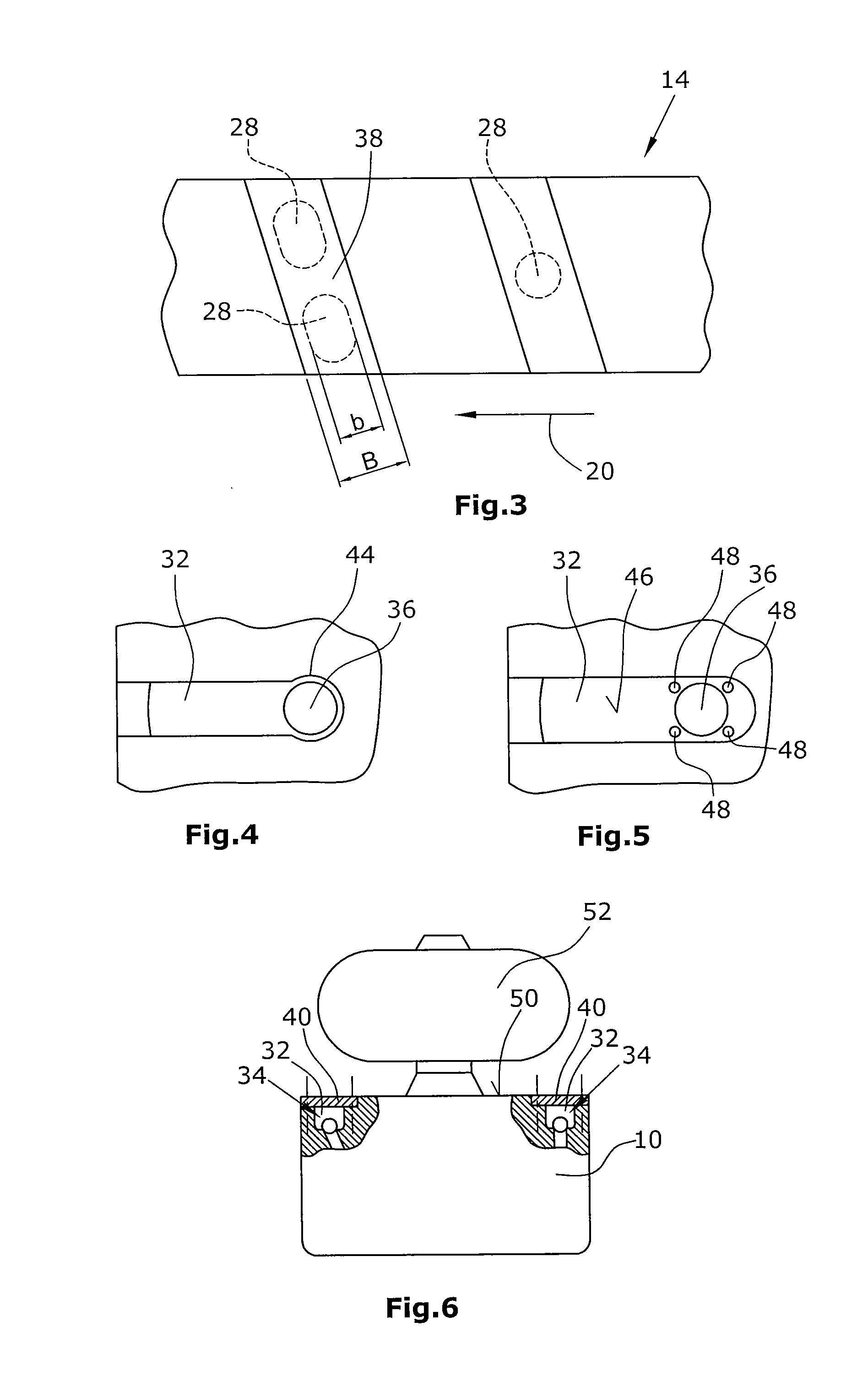
[0020]For a positional definition of the valve bodies it is advantageous, specifically for weight-loaded valve bodies, to provide holding elements which in a particularly preferred embodiment are arranged within the channel. In this context, it is preferred to provide pin-shaped holders, wherein a spherical valve body is held by preferably three or four correspondingly arranged pins. This has the particular
advantage that the holder for the valve body can be designed in a simple manner. For instance, it is possible to provide the same housing with one or a plurality of longitudinally extending channels for different types of pumps and different applications. The position of the overpressure openings is then defined by subsequently forming corresponding bores. Likewise, the holding elements can also be set into the channel in a simple manner. It is thus possible to provide one pump housing for different types of pumps or different applications, in which the desired positions of the overpressure openings and the valves can be realized in a simple manner.
[0021]In another preferred embodiment of the disclosure, the width of the overpressure opening, seen in the longitudinal direction of the screw vacuum pump or in the conveying direction, is chosen such that it is smaller than or equal to the tooth width of the screw rotor. Preferably, this takes the position of the overpressure opening into account, since the tooth width of the screw vacuum rotor may vary in the longitudinal direction. The reduction of the maximum width of the overpressure opening in the longitudinal direction, as provided by the disclosure, reduces an overflowing over the tooth of the screw rotor in the area of the overpressure opening. Thus, the occurrence of return flows, i.e. the occurrence of flows against the conveying direction, is reduced so that the pumping performance is not or only slightly reduced by providing an overpressure opening. This is particularly relevant in the mode of operation in which the overpressure valve is closed and the maximum pumping performance of the screw vacuum pump is to be achieved. Here, the width of the overpressure opening in the longitudinal direction of the screw rotor is preferably smaller than or equal to 90%, in particular smaller than or equal to 80% of the tooth width in this area.

