Process Stream Decontamination Systems and Methods with Atomization Optimization

a technology of atomization optimization and stream decontamination, which is applied in the direction of liquid displacement, separation processes, instruments, etc., can solve the problems of pipeline corrosion, narrowing of the line, and narrowing of the pipeline, so as to achieve maximum pump performance, optimize the droplet size, and verify the effect of productivity

Inactive Publication Date: 2014-09-25
ENERGY FAB SOLUTIONS
View PDF1 Cites 0 Cited by
  • Summary
  • Abstract
  • Description
  • Claims
  • Application Information

AI Technical Summary

Benefits of technology

[0008]According to particular aspects, a decontamination system in accordance with the present invention introduces one or more selected decontaminants into the process stream by reducing a liquid containing the decontaminant to a spray of fine droplets (i.e., atomizing the liquid). In a described embodiment, the atomized decontaminant-containing liquid is introduced into the process stream when the process stream is in a gaseous state. The inventor has found that the use of an atomizing spray to introduce a decontaminant is highly effective and optimizes the contact time and amount of exposure which the process stream has to the decontaminant. In preferred embodiments, the atomizing spray has droplets that are no larger than 50 microns in diameter.
[0011]Decontamination systems in accordance with the present invention incorporate a system for optimizing the atomization of decontaminant to ensure that dispersion of decontaminant into the process stream is highly effective and that the decontaminant is atomized in a substantially complete manner. An exemplary optimization system in accordance with the present invention includes a pressure transmitter that is operably associated with each atomizer and which is adapted to detect a differential injection pressure for the atomizers and provide a controller with a signal indicative of the detected differential injection pressure. The collective signals from the pressure transmitter associated with each atomizer will verify productivity, efficiency and provide diagnostics for the atomization system. A pump flow meter is operably associated with the fluid pump to measure the injection rate of decontaminant and provide a signal indicative of the measured injection rate to a controller. The controller compares the signal received from the pump output meter to a preset baseline value to ensure maximum pump performance and provide maintenance diagnostic alarms. The atomization optimizing system helps to ensure that decontaminant liquid is atomized substantially completely and that droplet size is optimized.
[0012]In described embodiments, decontamination systems in accordance with the present invention include a recirculation mechanism. The recirculation mechanism allows for decontaminant to be reused in the system, thereby preventing waste and reducing the amount of spent decontaminant that must be transported and disposed of. In a described embodiment, the recirculation system mechanism includes a means for collecting used decontamination liquid, a chemical sensor, a recirculation pump and re-circulation tank for temporary storage of recirculated liquid. The chemical sensor monitors the decontaminant to determine the extent of usability relative to fresh decontaminant. As the decontaminant reacts with the contaminant, the usability decreases. The unusable portion is said to be spent or saturated. The chemical sensor determines if reinjection is possible or, alternatively, if dumping to the waste tank is required.
[0014]A decontamination system in accordance with the present invention is capable of accurately and continuously monitoring, identifying and quantifying contaminants. The system can sample the process stream continuously at one or more sampling points and route the samples to one or more analyzers to provide real time measurement of contaminant concentration. The system will log contaminant measurements and manage this data via the controller. The controller can automatically adjust the amount of decontaminant that is added to the vaporization vessel in response to detection of an elevated (or reduced) amount of contaminant in the process stream. In a described embodiment, the amount of decontaminant is adjusted by controlling the rate of fluid flow provided by the fluid pump.

Problems solved by technology

These contaminants can cause pipeline corrosion and subsequent rupture, narrowing of the line due to deposits, plugging, precipitation of solids, etc.
Hydrogen sulfide is not only harmful to humans, but when left untreated, can quickly corrode pipelines, potentially leading to ruptures and explosions.
This is an extremely low concentration and can be difficult to measure accurately.
Conventional methods for treatment of contaminants have drawbacks.
Inaccuracies in measurement of the contaminant frequently lead to overuse of injected curative.
Operators routinely overcompensate when attempting to mitigate a risk by injecting excess chemical into the process stream.
Because chemicals can be expensive, overuse translates into significant financial waste.
Additionally, high levels of excess chemical can accumulate and must be removed or can build up on the pipeline wall, creating a rock-hard scale.
Under certain conditions, rock hard scale builds up and can restrict the flow of gas causing further negative effects.
If too much scale accumulates, the pipeline will require treatment with other potentially hazardous and expensive chemicals resulting in further health and safety risks and monetary loss.

Method used


Image

  • Process Stream Decontamination Systems and Methods with Atomization Optimization
  • Process Stream Decontamination Systems and Methods with Atomization Optimization
  • Process Stream Decontamination Systems and Methods with Atomization Optimization

Examples


Embodiment Construction

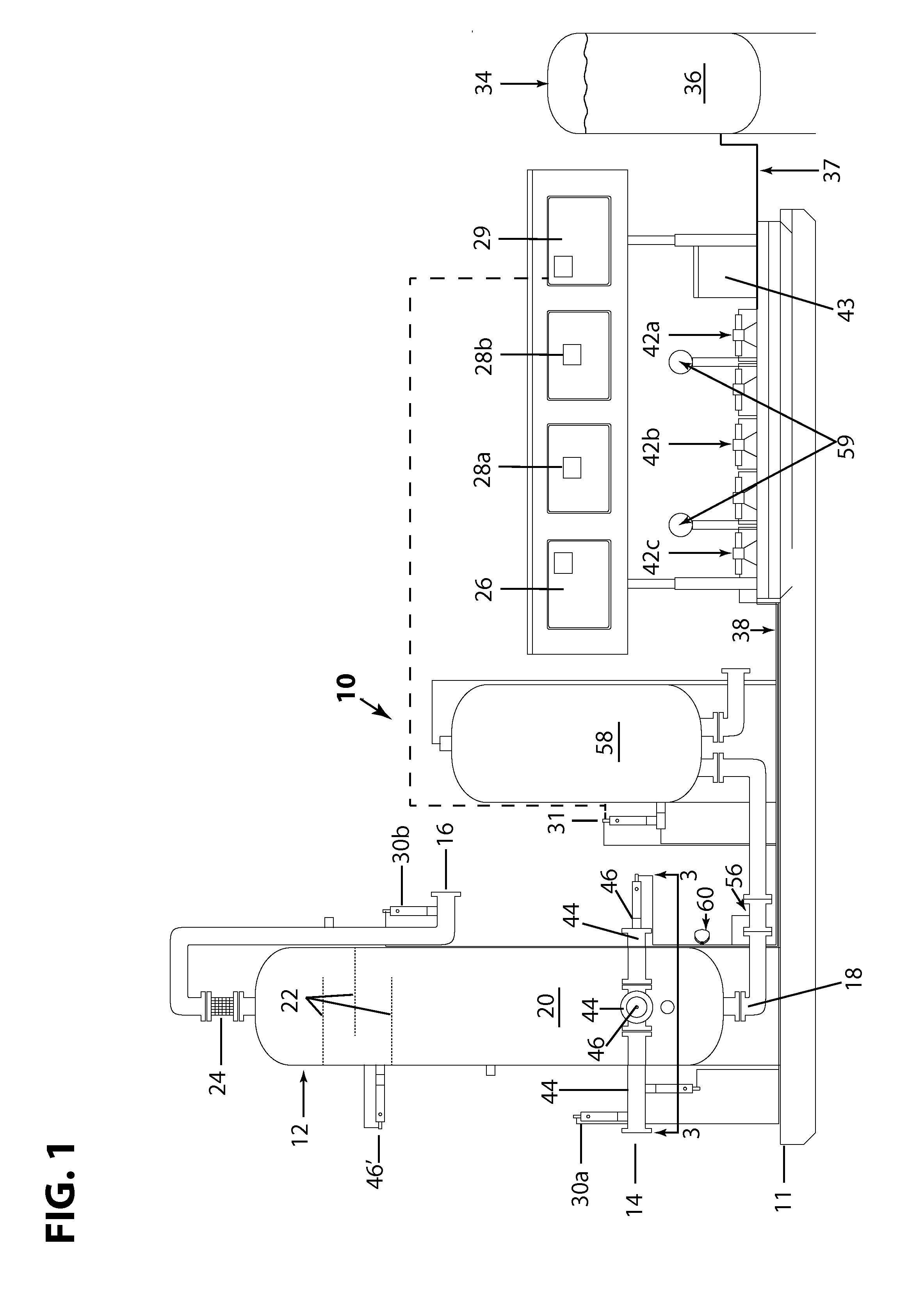
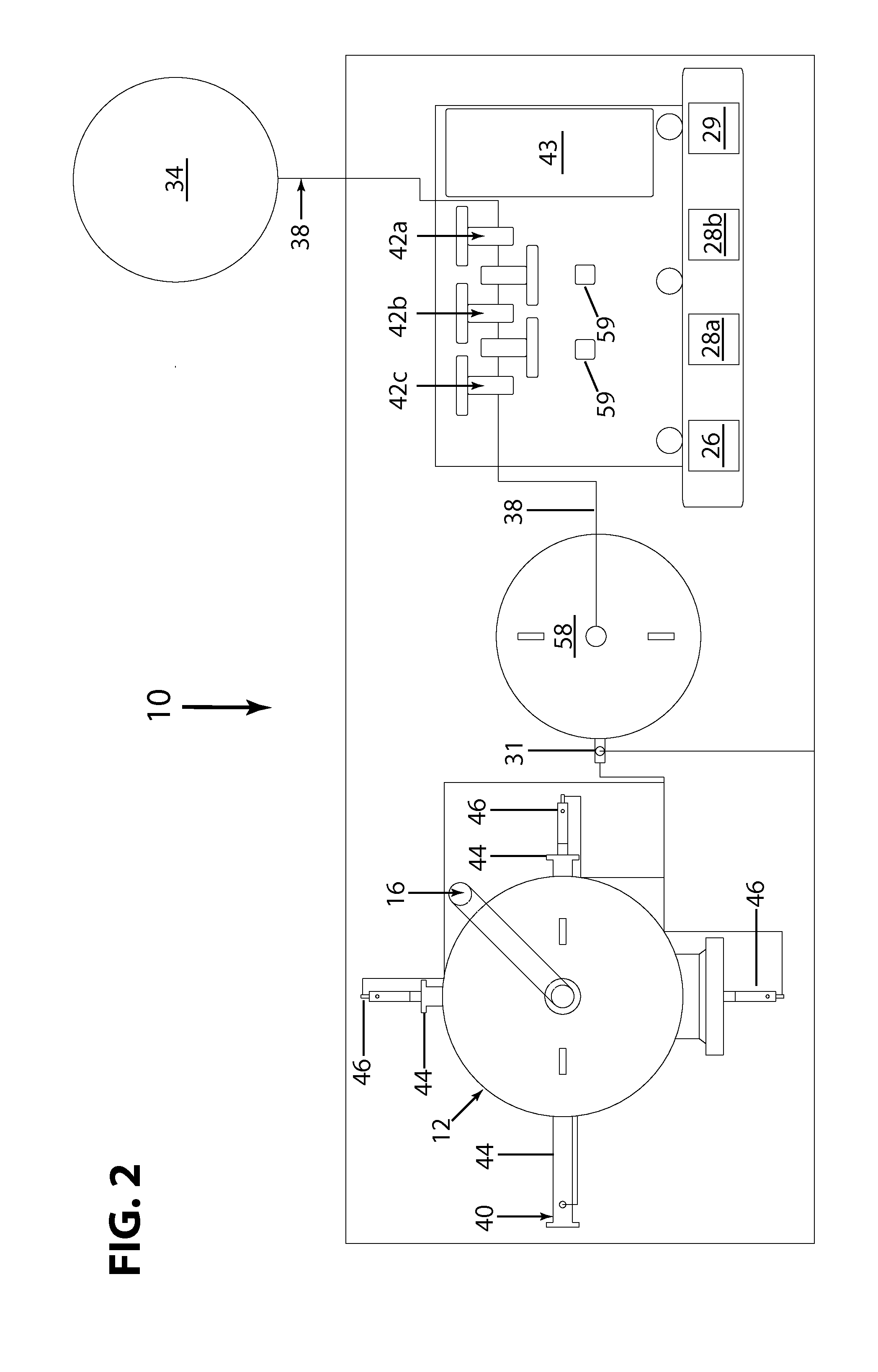
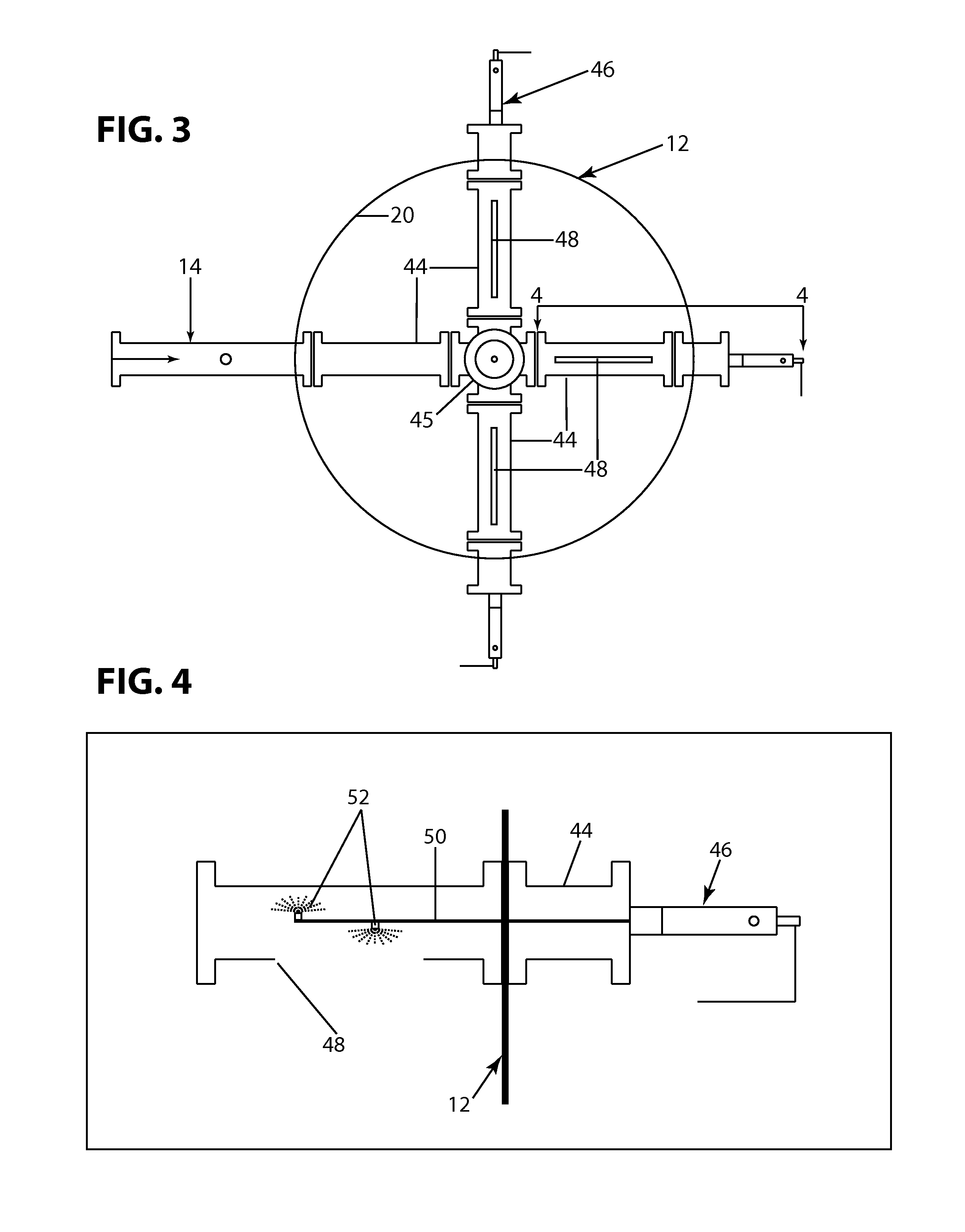
[0026]FIGS. 1 and 2 illustrate an exemplary decontamination system 10 that is constructed in accordance with the present invention. The decontamination system 10 is operably associated with a process stream that contains at least one contaminant of interest to be neutralized. In particular embodiments, the process stream can be natural gas flowing through a pipeline. The process stream could also be a flow of other liquids, such as crude oil or water. Typical contaminants include hydrogen sulfide (H2S), mercaptans, carbon dioxide (CO2), oxygen (O2), water (H2O) and biological populations. In addition, a detected “contaminant,” as discussed herein, can include conditions that can lead to contaminants, such as conditions that are ideal for hydrate formation or corrosion.

[0027]In certain embodiments, the decontamination system 10 of the present invention can be configured as a portable, modular system that is designed to be readily moved and integrated into an existing facility having ...


PUM

PropertyMeasurementUnit
diameteraaaaaaaaaa
pressureaaaaaaaaaa
pressureaaaaaaaaaa

Abstract

A decontamination system for decontaminating at least one contaminant in a process stream. Decontaminant liquid is dispersed into the process stream sing atomization. Differential injection pressure and / or injection flow rate are monitored to help ensure that the atomization process is optimized.

Description

BACKGROUND OF THE INVENTION[0001]1. Field of the Invention[0002]The invention relates generally to systems and methods used to decontaminate process streams that contain at least one contaminant. In particular aspects, the invention relates to systems and methods for decontaminating natural gas, liquid petroleum products or water in pipelines or production streams and for monitoring and control of the decontamination process.[0003]2. Background of the Invention[0004]Regulations require companies that produce or supply natural gas, crude oil, liquid petroleum gas or water to monitor product contaminants, mitigate potential hazards and maintain quality specifications. Typical contaminants include hydrogen sulfide (H2S), carbon dioxide (CO2), oxygen (O2), and biological populations. These contaminants can cause pipeline corrosion and subsequent rupture, narrowing of the line due to deposits, plugging, precipitation of solids, etc. Hydrogen sulfide, for example, is a highly corrosive an...

Claims


Application Information

Patent Timeline
Patent Type & Authority Applications(United States)
IPC IPC(8): A61L2/24
CPCA61L2/24B01D12/00C10G29/00C02F1/00B01J19/0006B01J2219/00065B01J2219/00069B01J2219/00162B01J2219/00164B01J2219/00198B01J2219/002B01J2219/00213B01J2219/0022B01J2219/00225
Inventor WITT, LANCE
Owner ENERGY FAB SOLUTIONS
Why Eureka
Try Eureka