Side airbag device

Active Publication Date: 2019-08-08
MAZDA MOTOR CORP +1
View PDF8 Cites 4 Cited by
  • Summary
  • Abstract
  • Description
  • Claims
  • Application Information

AI Technical Summary

Benefits of technology

[0008]The invention can provide a side airbag device capable of appropriately protecting an occupant without a large impact on the chest of t

Problems solved by technology

Thus, the inner pressure in the airbag needs to be maintained at a high level for a long period of time.
In this case, the reaction force from the pressed airbag is appl

Method used


Image

  • Side airbag device
  • Side airbag device
  • Side airbag device

Examples


embodiment 1

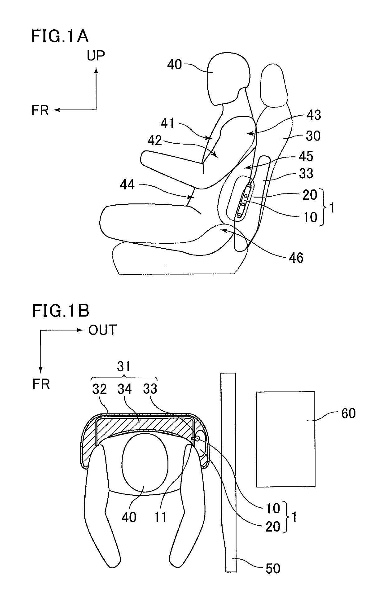
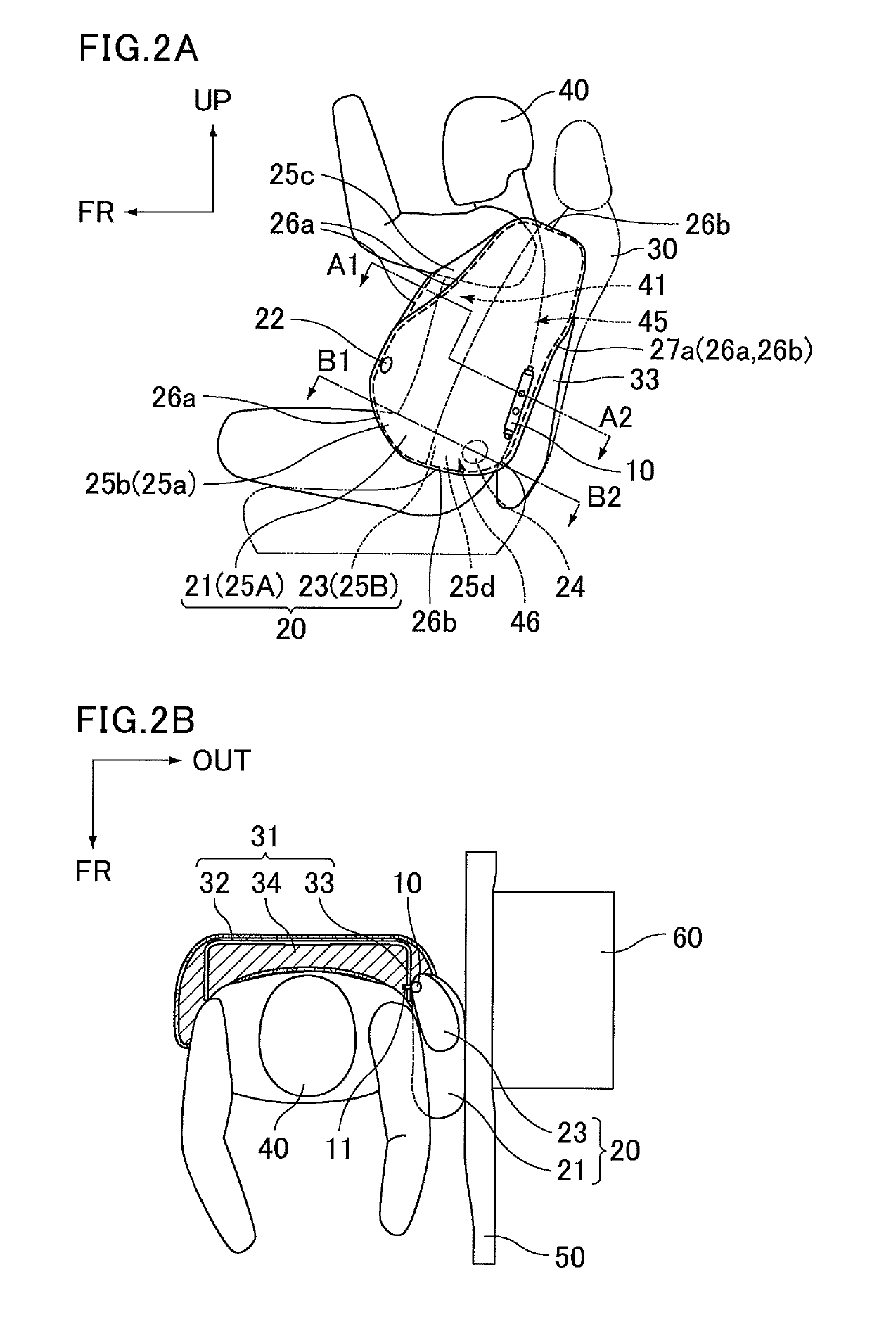
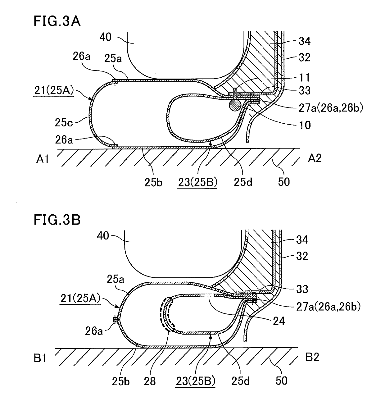
[0029]A side airbag device of Embodiment 1 is described below with reference to the drawings, with the inflating and deploying behavior of the side airbag being focused on. The directions and sides herein are described relative to a vehicle unless otherwise mentioned. For example, the “front side” indicates a side based on the forward direction of a vehicle; the “rear side” indicates a side based on the backward direction of a vehicle; the “upper side” indicates a side based on the upward direction of a vehicle; the “lower side” indicates a side based on the downward direction of a vehicle; and the “outer side” indicates a side based on the outward direction of the width direction of a vehicle. The arrow FR, the arrow UP, and the arrow OUT drawn in the figures as appropriate respectively indicate the forward direction of a vehicle, the upward direction of a vehicle, and the outward direction of the width direction of a vehicle. The members placed inside a vehicle seat are illustrate...

embodiment 2

[0067]A side airbag device of Embodiment 2 is described below with reference to the drawings, with the inflating and deploying behavior of the side airbag being focused on. The side airbag device of Embodiment 2 is similar to the side airbag device of Embodiment 1, except for the structure of the inner bag. The same features therefore will not be elaborated upon here.

(Before Inflation and Deployment)

[0068]The side airbag 20 before inflation and deployment is similar to that described with reference to FIG. 1.

(Early Stage of Occupant Restriction)

[0069]FIGS. 11A and 11B are schematic views of the side airbag device of Embodiment 2 in an early stage of occupant restriction by the side airbag; FIG. 11A shows a state seen from an outer side and FIG. 11B shows a state seen from an upper side. FIGS. 12A and 12B are schematic cross-sectional views taken along the lines in FIG. 11A; FIG. 12A is a cross-sectional view taken along the line A1-A2 and FIG. 12B is a cross-sectional view taken alo...

embodiment 3

[0082]A side airbag device of Embodiment 3 is described below with reference to the drawings. The side airbag device of Embodiment 3 is similar to the side airbag device of Embodiment 1, except for the structure of the inner bag. The same features therefore will not be elaborated upon here.

[0083]Hereinabove, the occupant 40 described is a world side impact dummy seated in the vehicle seat 30. Still, more specifically, a WS50-type world side impact dummy which simulates an occupant with a standard somatotype may be seated in the vehicle seat 30 in some cases, while a WS5-type world side impact dummy which simulates an occupant with a small somatotype may be seated in the vehicle seat 30 in other cases. FIG. 17 is a schematic view of a side airbag device of Embodiment 3 in a middle stage of occupant restriction by the side airbag with a WS50-type world side impact dummy seated in a vehicle seat. FIG. 18 is a schematic view of a side airbag device of Embodiment 3 in a middle stage of o...


PUM


Abstract

The side airbag device includes an inflator and a side airbag that is stored in a folded state in a side portion of a seatback of a vehicle seat and is inflatable and deployable in a space between a vehicle sidewall and a side portion of an occupant. The side airbag includes an outer bag and an inner bag. The inner bag houses the inflator and is disposed at a rear portion of the outer bag along an extending direction of the seatback. The outer bag is provided with a vent hole configured to communicate with an outside. The inner bag is provided with a gas circulating hole configured to communicate with the outer bag. The gas circulating hole is disposed at a position to be blocked by the outer bag when the side airbag in an inflated and deployed state is pressed between the occupant and the vehicle sidewall.

Description

CROSS-REFERENCE TO RELATED APPLICATIONS[0001]The present application claims priority under 35 U.S.C. § 119 to Japanese Patent Application No. 2018-019364 filed on Feb. 6, 2018, the contents of which are incorporated herein by reference in their entirety.BACKGROUND OF THE INVENTIONField of the Invention[0002]The invention relates to a side airbag device. The invention specifically relates to a side airbag device that inflates and deploys to protect an occupant in case of a lateral collision of a vehicle such as an automobile.Discussion of the Background[0003]Side airbag devices are devices configured to deploy a side airbag inflated by a gas introduced thereinto toward the vehicle sidewall side of an occupant seated in a vehicle seat to protect, in a lateral collision of a vehicle, a side portion of the occupant from a sidewall of a struck vehicle intruding into an interior of the struck vehicle.[0004]For example, U.S. Pat. No. 8,714,588 discloses a side airbag device for improving t...

Claims


Application Information

Patent Timeline
IPC IPC(8): B60R21/233B60R21/264B60R21/237B60R21/207B60R21/239B60R21/235B60R21/2334
CPCB60R21/233B60R21/264B60R21/237B60R21/207B60R21/239B60R21/235B60R21/2334B60R2021/0006B60R2021/0032B60R2021/23509B60R2021/23324B60R2021/0055B60R2021/0058B60R21/23138B60R2021/23146B60R2021/23332
Inventor OKADA, SHINJISUGIMURA, YUICHIAZUMA, HIDETAKAYAMAMURA, TAKAHIKOYOKOMI, ICHIROHAMADA, TETSURO
Owner MAZDA MOTOR CORP
Why Eureka
Try Eureka