Electronic circuit and in-ear piece for a hearing device

a technology of in-ear piece and electronic circuit, which is applied in the direction of valve details, earpiece/earphone mechanical/electrical switches, and electromagnets. it can solve the problems of backward compatibility problems between the hearing instrument and the new in-ear piece, the functionality of the in-ear piece, and the need for a new connector. it can reduce the generation of impact nois

Active Publication Date: 2019-08-08
SONION NEDERLAND
View PDF0 Cites 10 Cited by
  • Summary
  • Abstract
  • Description
  • Claims
  • Application Information

AI Technical Summary

Benefits of technology

[0029]providing a drive signal to the controllable acoustic valve, said drive signal comprising a first and a second part, wherein the drive signal, in the first part, is adapted to overcome a retention force of a first essentially stable state in order to initiate movement of the moveable valve element from the first essentially stable state to a second essentially stable state, and wherein the drive signal, in the second part, is adapted to decelerate the movement of the moveable valve element before it reaches the second essentially stable state in order to reduce generation of impact noise.
[0030]Thus, according to the second aspect the provided drive signal may comprise a first part adapted to overcome a retention force of a first essentially stable state, and a second part adapted to slow down or decelerate the moveable valve element before it reaches its destination in order to reduce generation of impact noise, such as click and contact noise.

Problems solved by technology

The number of wires between a hearing instrument and an in-ear piece should be limited for various reasons, including:a limited number of wires can be hidden in a thin cable that can be made almost invisible for cosmetic reasons, andthe functionality of the in-ear piece has so far been limited in that only a microphone or a speaker should be supported
This is disadvantageous in that it may result in a need for a new connector between the hearing instrument and the in-ear piece.
Such a new connector will typically result in backwards compatibility problems between the hearing instrument and new in-ear pieces.
Moreover, a processor of a hearing instrument may not necessarily have additional ports to control or monitor such one or more additional components of an in-ear piece.
Even further, the available port(s) on the processor of the hearing instrument, which are normally dedicated to drive a speaker of the in-ear piece, is / are not necessarily compatible with the interface to such one or more additional components.
Obviously, hearing device manufactures tend to avoid the above situation as it is highly disadvantageous.

Method used


Image

  • Electronic circuit and in-ear piece for a hearing device
  • Electronic circuit and in-ear piece for a hearing device
  • Electronic circuit and in-ear piece for a hearing device

Examples


Embodiment Construction

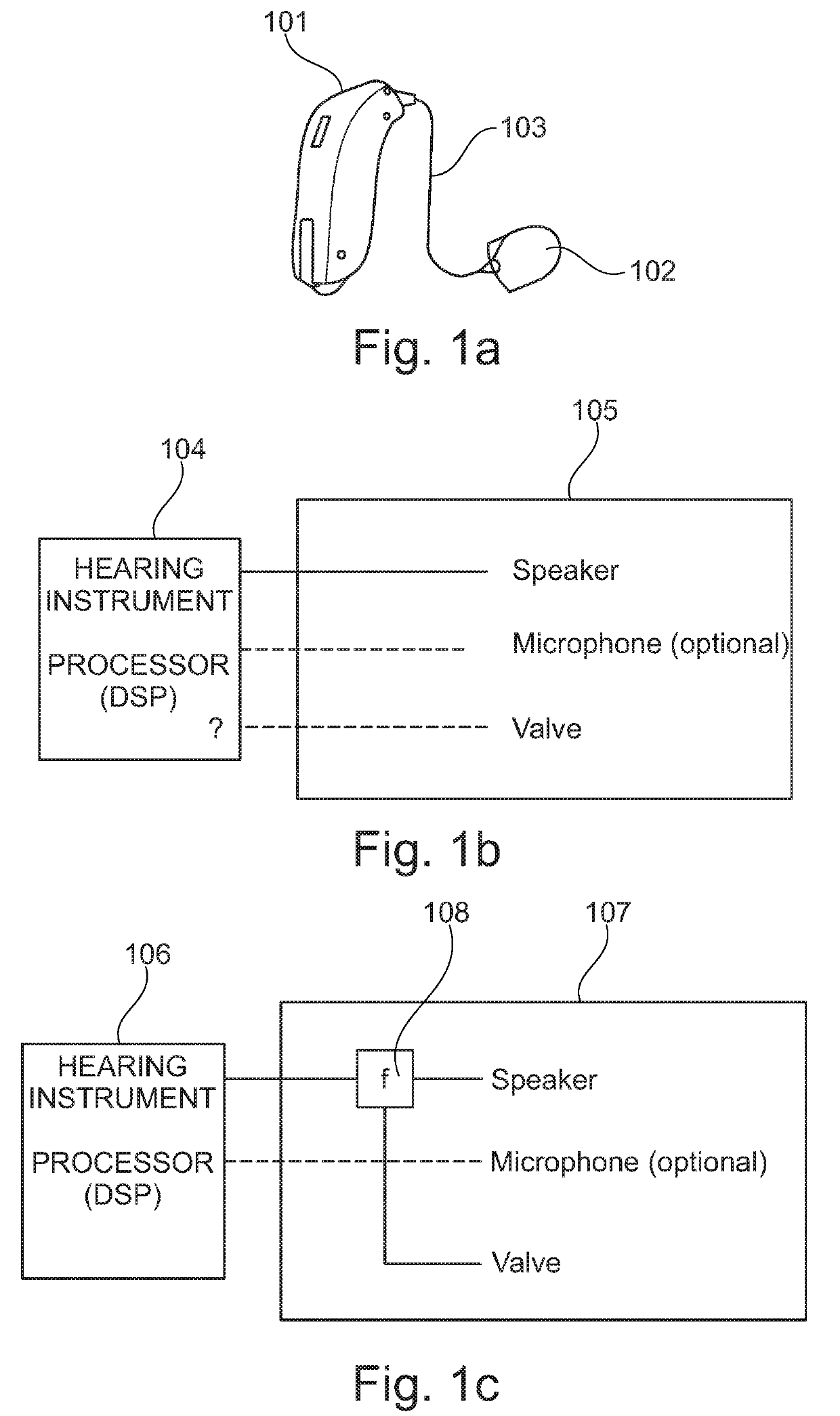
[0106]Referring now to FIG. 1a a hearing device comprising a hearing instrument 101 and an in-ear piece 102 is depicted. The hearing instrument 101 is adapted to be positioned behind the ear of the user of the hearing device, whereas the in-ear piece 102 is adapted to be positioned at least partly in the ear canal of the user of the hearing device. The hearing instrument 101 and the in-ear piece 102 is electrically interconnected by a number of electrical wires 103 so that one or more electrical signals may be exchanged between the hearing instrument 101 and the in-ear piece 102. The number of wires interconnecting the hearing instrument 101 and the in-ear piece 102 does not exceed three electrical wires, thus including a single twisted pairs of wires.

[0107]As shown in FIG. 1b the hearing instrument 104 comprises a digital signal processor (DSP). The in-ear piece 105 comprises a speaker, an acoustic valve and an optional microphone. A speaker, an acoustic valve and a microphone woul...


PUM

PropertyMeasurementUnit
forceaaaaaaaaaa
retention forcesaaaaaaaaaa
retention forceaaaaaaaaaa

Abstract

A method for controlling a controllable acoustic valve of a hearing device. The valve includes a moveable valve element adapted to be positioned in one of at least two essentially stable states. The moveable valve element is configured to be maintained in each of the essentially stable states by a retention force. A neutral point with essentially cancelling retention forces exists between the least two essentially stable states. The method includes providing a first drive signal to the controllable acoustic valve to overcome a retention force of a first essentially stable state in order to initiate movement of the moveable valve element from the first essentially stable state to a second essentially stable state. The provided first drive signal is capable of bringing the moveable valve element from the first essentially stable state and beyond a neutral point between the first and second essentially stable states.

Description

CROSS-REFERENCE TO RELATED APPLICATIONS[0001]This application claims the benefit of European Patent Application Serial No. 18155316.5, filed Feb. 6, 2018, which is incorporated herein by reference in its entirety.FIELD OF THE INVENTION[0002]The present invention relates to an electronic circuit and an in-ear piece for a hearing device. In particular, the present invention relates to an electronic circuit and a method for controlling a hearing device and an in-ear piece comprising a speaker and a controllable acoustic valve. The electronic circuit and the in-ear piece of the present invention are configured to be electrically connected to other devices of the hearing device via a maximum of three electrical wires.BACKGROUND OF THE INVENTION[0003]Hearing devices may be implemented in various ways, including implementations where a hearing instrument is positioned behind the ear, whereas an in-ear piece is at least partly positioned in the ear canal. The hearing instrument and the in-e...

Claims


Application Information

Patent Timeline
Patent Type & Authority Applications(United States)
IPC IPC(8): H04R25/00H01F7/06F16K31/06F16K11/07
CPCH04R25/505H01F7/064F16K31/0613F16K11/0716H04R2225/61H04R1/1041
Inventor LAFORT, ADRIANUS MARIABOLSMAN, CASPAR TITUSMAAS, RENEBROUWER, THEODORUS GERADUS MARIAGAO, YANG
Owner SONION NEDERLAND
Why Eureka
Try Eureka