Tubeless air valve stem
a technology of air valve stem and tubeless tire, which is applied in the direction of transportation and packaging, vehicle components, thin material processing, etc., can solve the problem that gas cannot be injected into the tubeless tire via and achieve the effect of reducing the gas quantity of the conventional air valve stem
- Summary
- Abstract
- Description
- Claims
- Application Information
AI Technical Summary
Benefits of technology
Problems solved by technology
Method used
Image

Examples
first embodiment
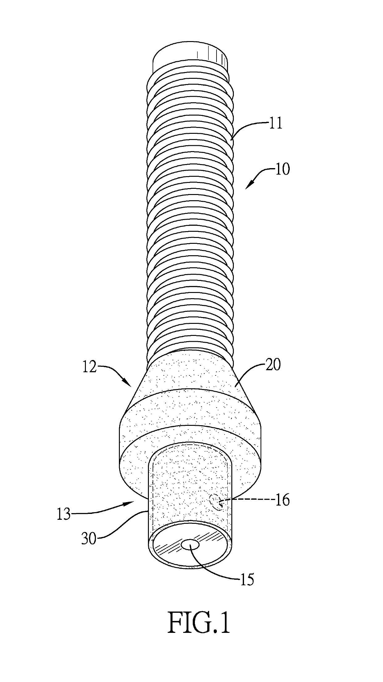
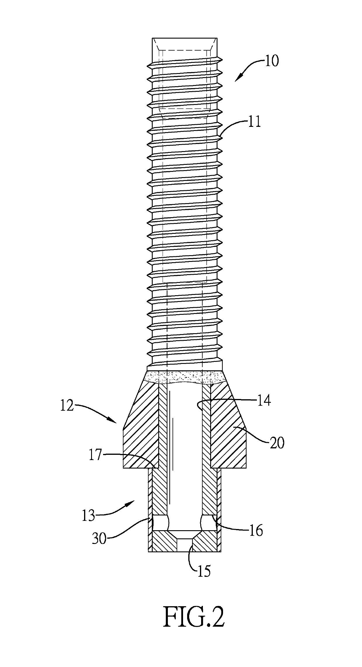
[0025]With reference to FIGS. 1 and 2, the tubeless air valve stem in accordance with the present invention comprises a body 10, an airtight element 20, and a sleeve 30.
[0026]With reference to FIGS. 1 and 2, the body 10 has a top end, a bottom end, an outer surface, a threaded portion 11, a connecting portion 12, a bypassing portion 13, a passage 14, a through hole 15, and at least one side hole 16. The threaded portion 11 is formed on the outer surface of the body 10 and is connected to the top end of the body 10. The connecting portion 12 is formed on the outer surface of the body 10 below the threaded portion 11. The bypassing portion 13 is formed on the outer surface of the body 10 below the connecting portion 12, is connected to the bottom end of the body 10, and has an outer surface. The passage 14 is formed through the top end of the body 10 and extends to the bypassing portion 13. The through hole 15 is formed through the bottom end of the body 10, extends toward the top end...
second embodiment
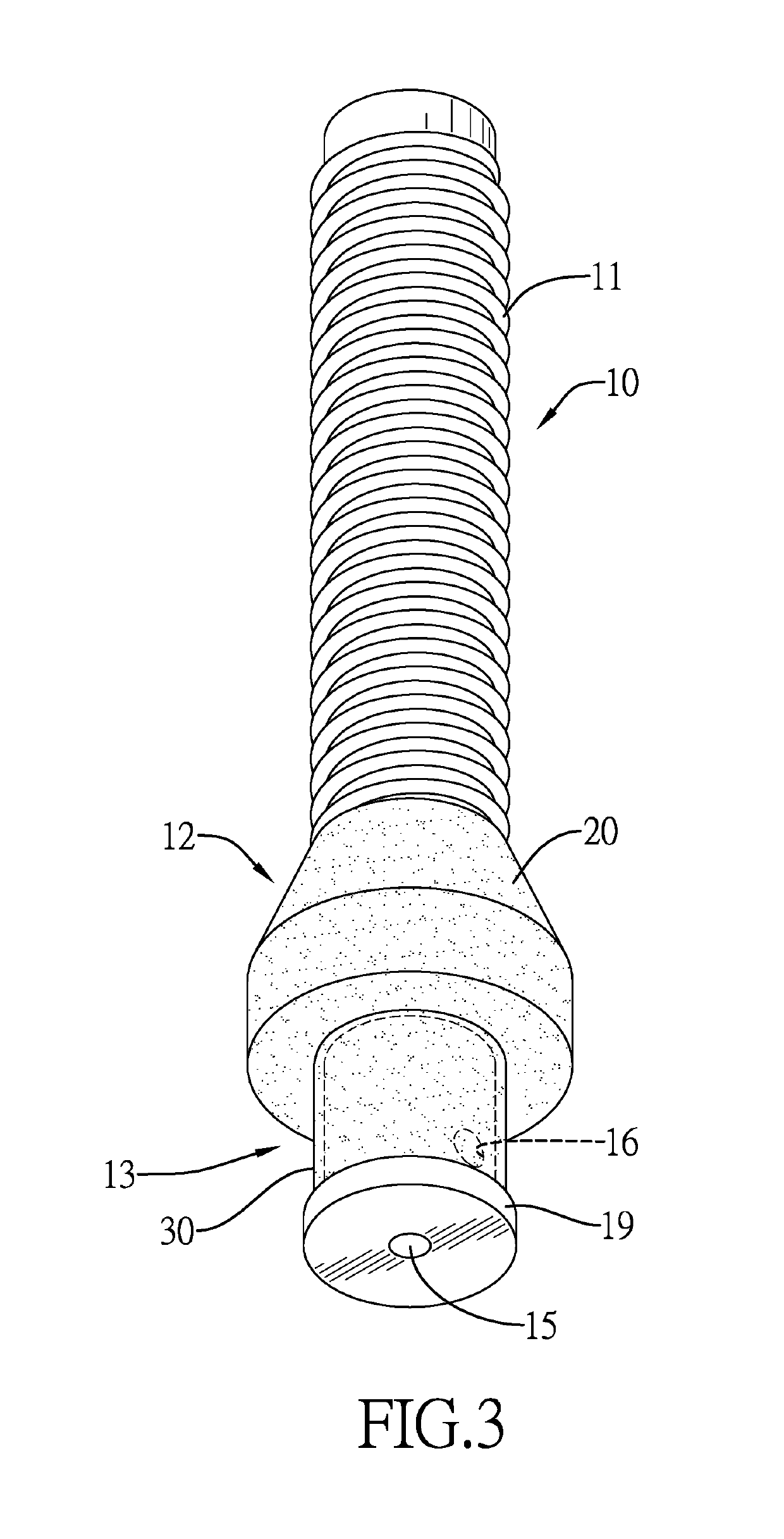
[0031]With reference to FIGS. 3 and 4, in the tubeless air valve stem, the body 10 has a flange 19. The flange 19 is formed on and is protruded from a bottom end of the bypassing portion 13. A bottom end of the sleeve 30 abuts the flange 19. A longitudinal cross section of the flange 19 may be square or arced in shape.
third embodiment
[0032]With reference to FIGS. 5 and 6, in the third embodiment, the body 10 has a slip-proof protrusion 18. The slip-proof protrusion 18 is formed on and protrudes from the outer surface of the bypassing portion 13. The sleeve 30 covers and engages with the slip-proof protrusion 18. A longitudinal cross section of the slip-proof protrusion 18 may be square or arced in shape.
[0033]With reference to FIGS. 7 to 10, in the fourth embodiment, the fifth embodiment, and the sixth embodiment of the tubeless air valve stem, the body 10 has a flange 19. The flange 19 is formed on and is protruded from a bottom end of the bypassing portion 13. The body 10 has a slip-proof protrusion 18. The slip-proof protrusion 18 is formed on and is protruded from an outer surface of the bypassing portion 13. The sleeve 30 covers and engages with the slip-proof protrusion 18. A bottom end of the sleeve 30 abuts the flange 19. A longitudinal cross section of the flange 19 is square or arched in shape, but it ...
PUM
 Abstract
Description
Claims
Application Information
 - R&D
- Intellectual Property
- Life Sciences
- Materials
- Tech Scout
- Unparalleled Data Quality
- Higher Quality Content
- 60% Fewer Hallucinations
Browse by: Latest US Patents, China's latest patents, Technical Efficacy Thesaurus, Application Domain, Technology Topic, Popular Technical Reports.
© 2025 PatSnap. All rights reserved.Legal|Privacy policy|Modern Slavery Act Transparency Statement|Sitemap|About US| Contact US: help@patsnap.com