Fuel cell system

a fuel cell and system technology, applied in the field of fuel cell systems, can solve the problems of degrading the fuel cell and difficulty in simplifying the layout of the fuel cell system, and achieve the effects of preventing the degradation of the components of the fuel cell stack, suppressing local generation of electric potential and heat, and reducing the amount of gas mixture of remaining oxygen

Active Publication Date: 2006-01-12
NISSAN MOTOR CO LTD
View PDF6 Cites 22 Cited by
  • Summary
  • Abstract
  • Description
  • Claims
  • Application Information

AI Technical Summary

Benefits of technology

[0006] The fuel cell system according to the present invention is capable of reducing the amount of gas mixture of remaining oxygen and hydrogen and suppressing local generation of electric potential and heat due to the reaction of the gas mixture on the anode catalyst. It is therefore possible to prevent degradation of the components of a fuel cell stack. The fuel cell system does not discharge hydrogen when activated and does not need to include dilution equipment or combustion equipment for dealing with hydrogen, thus increasing the degree of freedom in the layout of the fuel cell system.

Problems solved by technology

However, when the anode operating pressure is increased during activation of the fuel cell like the conventional fuel cell system, the gas mixture reacts on an anode catalyst, and electric potential and heat are locally generated, thus degrading the fuel cell.
Furthermore, the fuel gas is discharged together with the nitrogen gas and gas mixture, and dilution equipment or combustion equipment is required for treating the fuel gas, which makes it difficult to simplify the layout of the fuel cell system.

Method used


Image

  • Fuel cell system
  • Fuel cell system
  • Fuel cell system

Examples


first embodiment

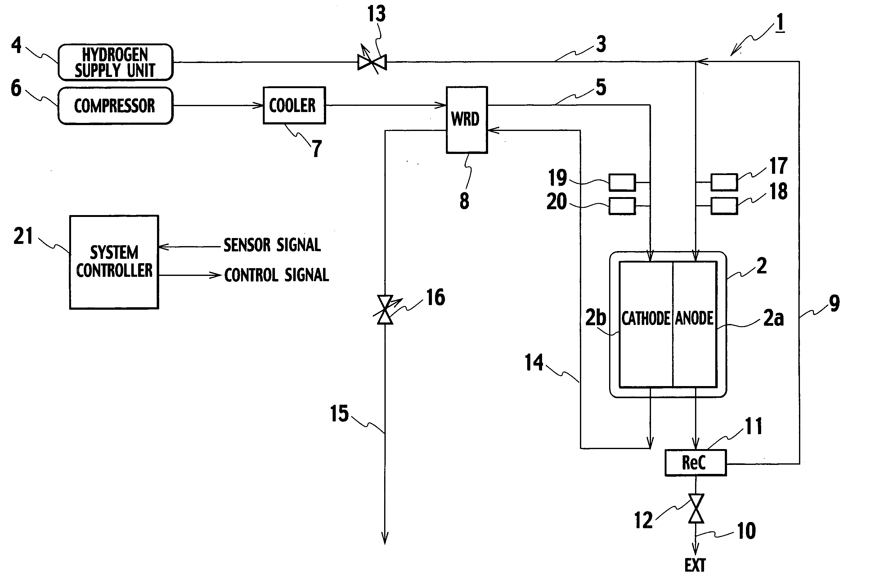
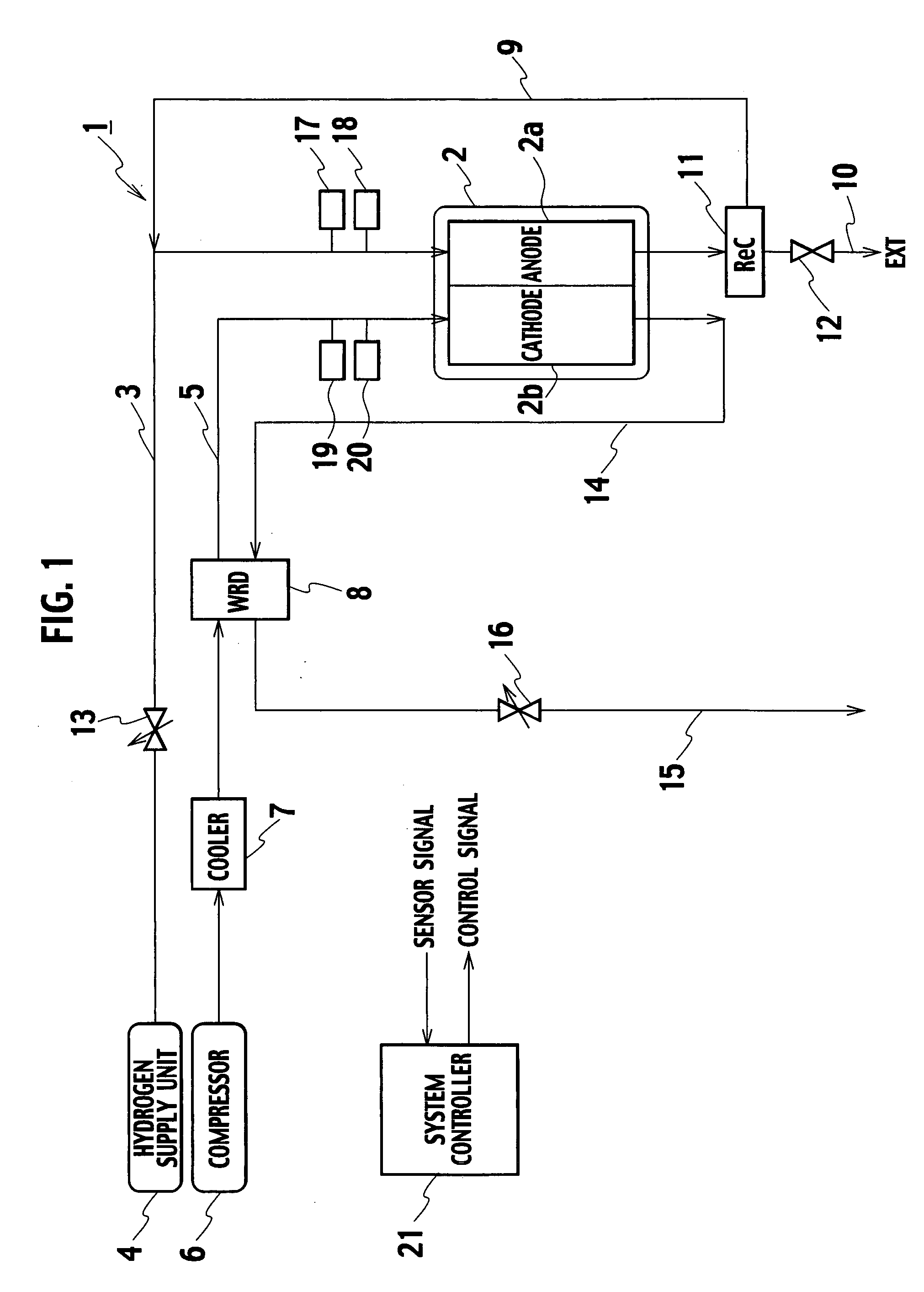
[0034] A fuel cell system 1 as the present invention includes, as shown in FIG. 1, a fuel cell stack 2, a hydrogen supply unit 4, a compressor 6, an aftercooler 7, and a humidifier unit 8. The fuel cell stack 2 includes a plurality of fuel cells stacked, and the fuel cells generate electricity using hydrogen and air. The hydrogen supply unit 4 supplies hydrogen to an anode 2a of the fuel cell stack 2 through a hydrogen supply pipe 3. The compressor 6 supplies air to a cathode 2b of the fuel cell stack 2 through an air supply pipe 5. The aftercooler 7 cools the air supplied to the cathode 2b to a temperature suitable for power generation of the fuel cells. The humidifier unit 8 humidifies the air supplied to the cathode 2b.

[0035] The fuel cell system 1 further includes a gas circulator 11, a purge valve 12, a pressure regulating valve 13, a pipe 14, an exhaust pipe 15, and a pressure regulating valve 16. The gas circulator 11 circulates hydrogen which has not been consumed and disch...

second embodiment

[0054] As apparent from the above description, according to the fuel cell system 31 as the present invention, the system controller 21 increases the anode operating pressure after the oxygen concentration in the anode circulation path 9 decreases to such an oxygen concentration that degradation of the components of the fuel cell stack 2 is not caused. It is therefore possible to suppress degradation of the components of the fuel cell stack 2 even when the anode operating pressure is increased.

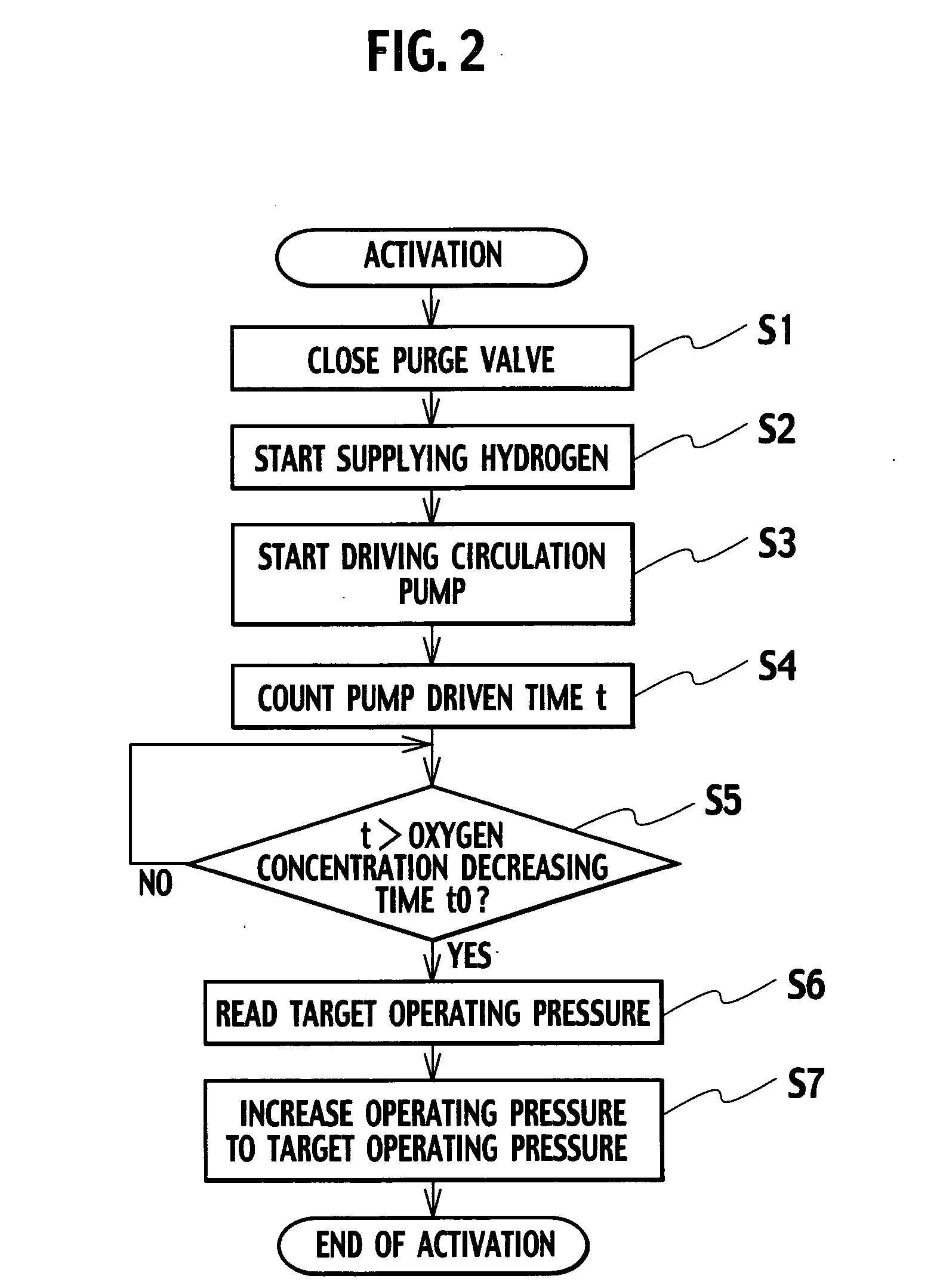
[0055] A fuel cell system as the third embodiment of the present invention has the same configuration as that of the fuel cell system as the second embodiment of the present invention. The system controller 21 executes the following activation process to prevent degradation of the components of the fuel cell stack 2 when the anode operating pressure is increased. Hereinafter, a description is given of an operation of the system controller 21 executing the activation process with reference to a ...

third embodiment

[0059] As apparent from the above description, according to the fuel cell system 31 as the present invention, the system controller 21 increases the anode operating pressure upon the oxygen concentration in the anode circulation path 9 being reduced to the predetermined oxygen concentration or less or upon the pump driven time t reaching the oxygen concentration decreasing time t0 or more. It is therefore possible to prevent degradation of the components of the fuel cell stack 2 even when the anode operating pressure is increased.

[0060] In a general fuel cell system, hydrogen, nitrogen, and vapor are mixed in the anode right after the system is stopped. When hydrogen in the anode is not discharged while the system is stopped, as shown in FIG. 7, the hydrogen concentration in the anode decreases over time because of crossover to the cathode, and on the other hand, the nitrogen concentration increases because of crossover from the cathode. The vapor concentration decreases as the temp...


PUM

PropertyMeasurementUnit
operating pressureaaaaaaaaaa
concentrationaaaaaaaaaa
concentration detectionaaaaaaaaaa

Abstract

A system controller drives a gas circulator with a purge valve closed to supply hydrogen to a fuel cell stack and then increases anode operating pressure and cathode operating pressure to target operating pressures after a predetermined condition is satisfied. This allows an amount of gas mixture of remaining oxygen and hydrogen to be suppressed compared to the case of increasing the anode operating pressure in a state where oxygen remains in the anode circulation path. Accordingly, it is possible to suppress local generation of electric potential and heat and prevent degradation of the components of the fuel cell stack. Moreover, hydrogen is not discharged during activation, which eliminates the need to include dilution equipment of combustion equipment for treating hydrogen and increases the degree of freedom in the layout of the fuel cell system.

Description

BACKGROUND OF THE INVENTION [0001] The present invention relates to a fuel cell system, and specifically, relates to a technology to activate a fuel cell without degrading components of the fuel cell and without discharging fuel gas to the outside. [0002] In a general polymer electrolyte fuel cell (hereinafter, abbreviated as a fuel cell), while power generation is stopped, oxidant gas flows from a cathode into an anode through a polymer electrolyte membrane, and a gas mixture of the oxidant gas and fuel gas is generated in the anode. In such a background, as disclosed in the Japanese Patent Laid-Open publication No. 11-97047, in a conventional fuel cell system, the oxidant gas and fuel gas are purged with nitrogen gas while power generation is stopped. In activation of the fuel cell, operating pressure on the anode side is increased, and then the oxidant gas is supplied to the cathode. Subsequently, an exhaust valve is opened to discharge the nitrogen gas and gas mixture remaining ...

Claims


Application Information

Patent Timeline
Patent Type & Authority Applications(United States)
IPC IPC(8): H01M8/04H01M8/24
CPCH01M8/04089H01M8/04126H01M8/04231H01M8/0432H01M8/04432Y02E60/50H01M8/04559H01M8/04604H01M8/04753H01M8/04761H01M2008/1095H01M8/04462
Inventor YONEKURA, KENJIIIO, MASATOSHI
Owner NISSAN MOTOR CO LTD
Why Eureka
Try Eureka