Sliding Door System

a sliding door and door technology, applied in the field of sliding doors, can solve the problems of losing the effectiveness of sealing, difficult sealing of sliding door systems, and wear of weather stripping, and achieve the effect of removing friction and wear from the seal

Active Publication Date: 2019-08-29
ARCONIC TECH LLC
View PDF8 Cites 10 Cited by
  • Summary
  • Abstract
  • Description
  • Claims
  • Application Information

AI Technical Summary

Benefits of technology

[0007]The present application discloses various embodiments of a sliding door assembly having a sliding door that moves laterally relative to a seal while remaining substantially perpendicular to an underlying floor in order to remove friction and wear from the seal when the sliding door is sliding.

Problems solved by technology

While sliding doors are desirable for space reasons, some sliding door systems are difficult to seal.
Accordingly, the weather stripping can wear rather quickly until it loses effectiveness at forming a seal.
If the unit is adjusted downward in order to close the gap too much, the added friction will not allow the panel to slide freely.
Moreover many of these types of systems do not have a way to reduce air infiltration at the header, typically they have some type of guide block in the header profile that guides the panel as it is sliding and only have some type of brush that glides against the panel.
Thus, many of these systems cannot be easily reconfigured to compensate for the wearing of the weather stripping, or the gradual shifting of a door frame.
Moreover, most of these systems cannot be adjusted via the wheels to compensate for a non-level floor.
On larger panels this becomes an issue due to the fact that the leading edge will not rest plumb against the jamb, which may prevent the panel interlockers from sealing and thereby allowing air infiltration.
However, attempts to combine automated open and closure systems with a system that lowers to seal can be cost prohibitive.
In certain instances, for example, the large handle required to leverage the heavy panels into the up and down positions that are mounted on each panel hinders the panel stack (e.g., many panels going in one direction) from stacking flush to each other in the open position.
Moreover, in some instances, large handles may prevent the panels from going all the way into the pocket.

Method used


Image

  • Sliding Door System
  • Sliding Door System
  • Sliding Door System

Examples


Embodiment Construction

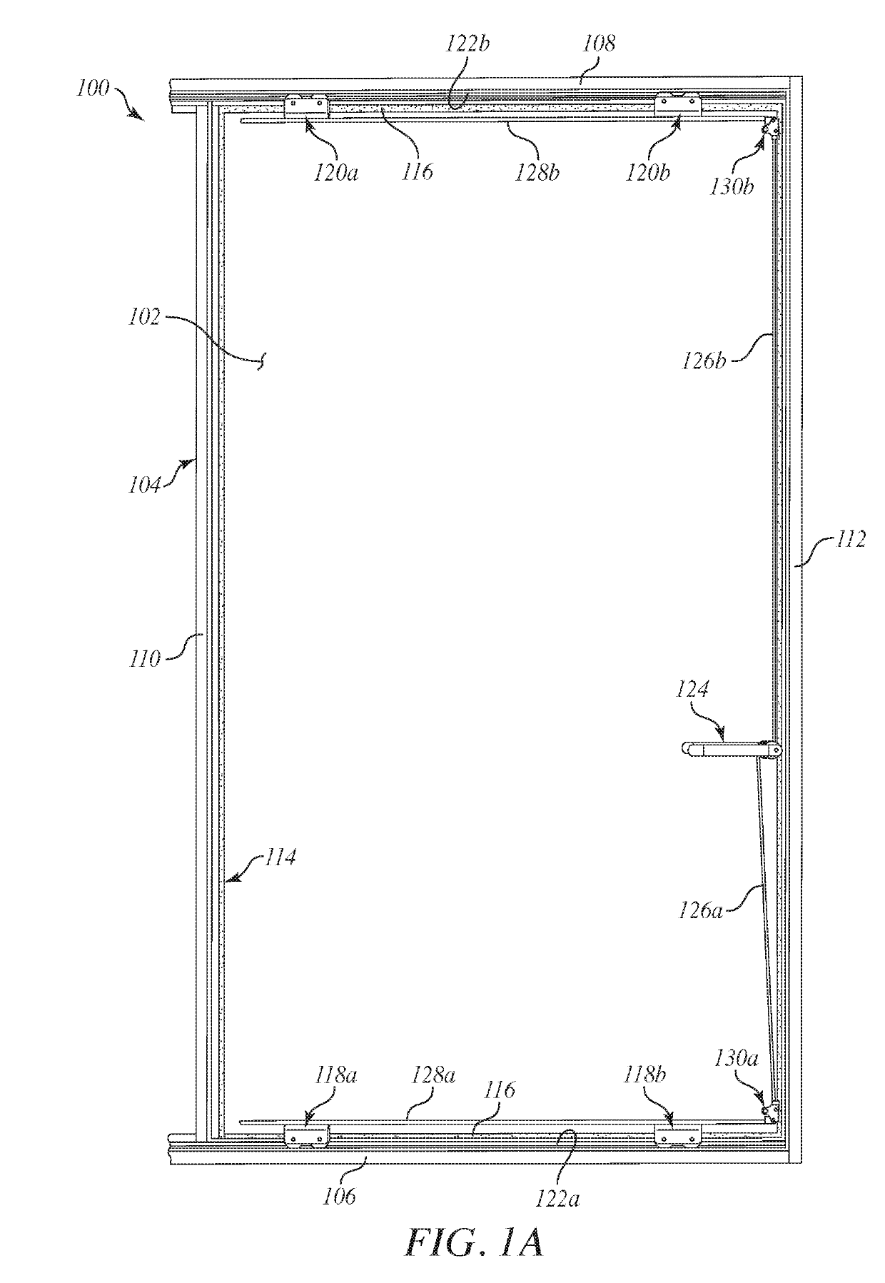
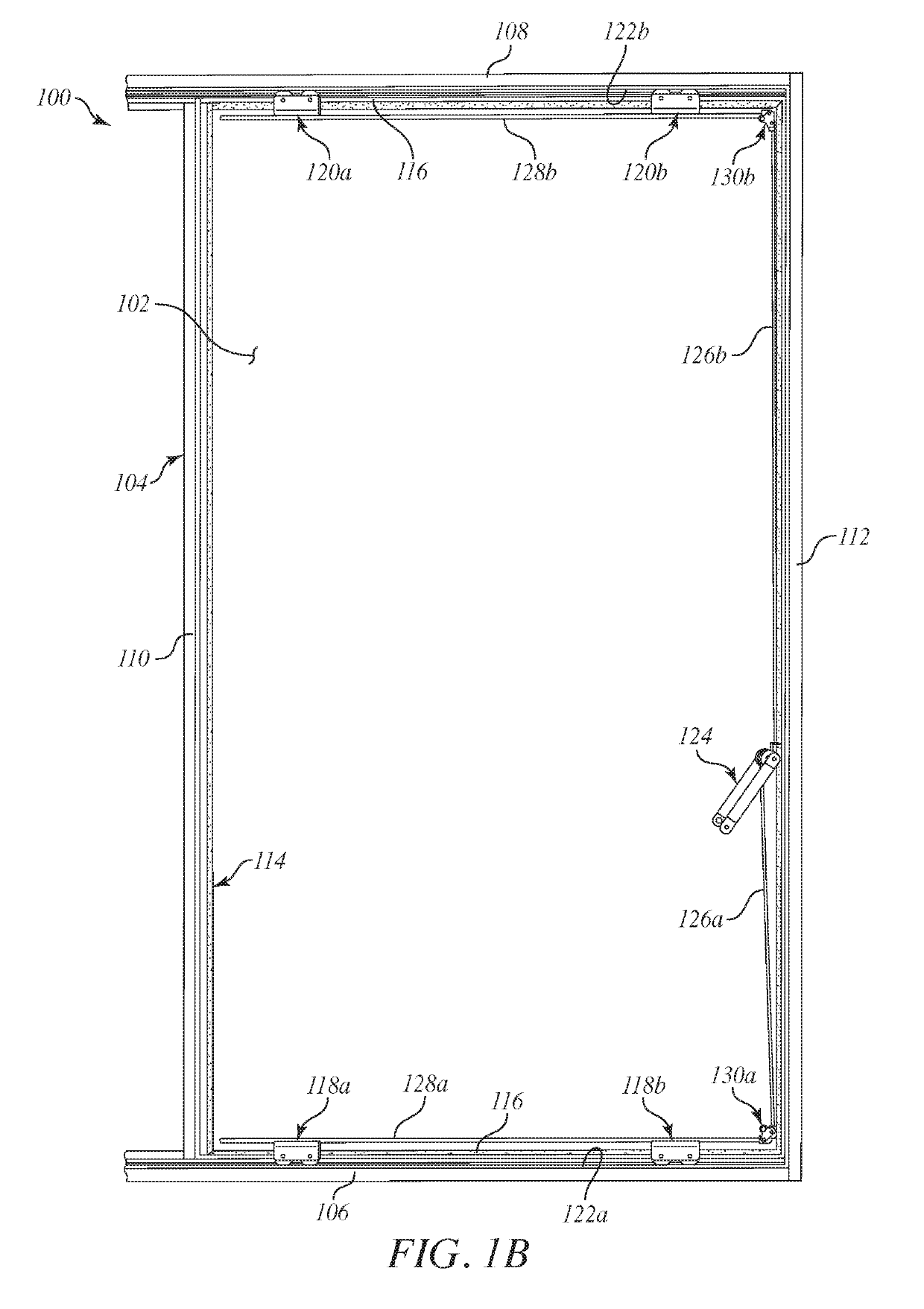
[0030]FIGS. 1A and 1B are partially exposed front views of an example sliding door assembly 100, according to one or more embodiments. More specifically, FIG. 1A shows the sliding door assembly 100 (hereafter the “assembly 100”) in a sealed position (alternately referred to as the “closed” position), and FIG. 1B shows the assembly 100 in a sliding position (alternately referred to as the “open” position). As illustrated, the assembly 100 includes a door panel 102 and a rectangular frame 104 that supports the door panel 102. In the illustrated view, the front portion of the door panel 102 is removed to expose the interior mechanisms and operation of the assembly 100.

[0031]The frame 104 includes a bottom member 106, a top member 108, and opposing side members 110 and 112 that extend between the bottom and top members 106, 108. A continuous or semi-continuous raised lip 114 may be provided and otherwise defined on some or all of the frame 104 and extend inward toward the center of the ...


PUM

PropertyMeasurementUnit
angleaaaaaaaaaa
constant biasing forceaaaaaaaaaa
frictionaaaaaaaaaa

Abstract

A sliding door assembly includes a door panel, a frame that supports the door panel and includes a bottom member with a lower profile and a top member with an upper profile, wherein the lower profile and the upper profile are parallel to one another. A lower sliding assembly is operatively coupled to a bottom of the door panel and engages the lower profile, and an upper sliding assembly is operatively coupled to a top of the door panel and engages the upper profile. A gasket interposes the door panel and a portion of the frame when the door panel is in a sealed position. The door panel is movable between the sealed position, where the gasket creates a sealed interface between the door panel and the frame, and a sliding position, where the door panel is moved laterally relative to the frame while remaining substantially perpendicular to a floor.

Description

FIELD OF THE INVENTION[0001]This application relates to sliding doors and, more specifically, to sliding door assemblies that include sliding assemblies capable of move a sliding door laterally relative to a seal.BACKGROUND OF THE INVENTION[0002]Sliding doors and other door systems are known in the art for providing means of restricting and permitting access to structures. Sliding doors can be advantageous over swinging doors because they can provide a large opening without requiring as much space for the doors to swing.[0003]While sliding doors are desirable for space reasons, some sliding door systems are difficult to seal. Many sliding door systems include some type of weather stripping or a brush along a lower edge of each door panel to form a seal with the floor surface. However, in order to effectively seal, these types of weather stripping or brushes must slide along the floor while the door system is being opened or closed. Accordingly, the weather stripping can wear rather ...

Claims


Application Information

Patent Timeline
Patent Type & Authority Applications(United States)
IPC IPC(8): E05D15/10E06B3/50E05D15/06E05D15/56
CPCE05D15/1042E06B3/50E05D15/0604E05D15/0665E05D15/56E06B7/23E05Y2900/132E05D2015/1049E05D2700/00E05Y2201/64E05Y2201/68E05Y2201/688E06B1/52E05D15/10E05D2015/1039E05Y2800/12E06B3/4636E06B7/2309E05D15/0652E05D15/0686E05D15/1044
Inventor TUMINELLA, JOSHHOOPER, WILLIAM J.BARBULESCU, ION-HORATIUMILLER, MATTHEW M.
Owner ARCONIC TECH LLC
Why Eureka
Try Eureka