Transmission control device for vehicle

a technology for transmission control and vehicles, which is applied in the direction of gearing control, gearing elements, belts/chains/gearrings, etc., can solve the problems of long-time torque interruption, impaired driving comfort of drivers, and impaired driving of drivers, so as to improve the degree of freedom of operation, improve the driving comfort, and improve the driving comfor

Active Publication Date: 2019-09-12
HITACHI ASTEMO LTD
View PDF0 Cites 3 Cited by
  • Summary
  • Abstract
  • Description
  • Claims
  • Application Information

AI Technical Summary

Benefits of technology

[0018]According to the present invention, since occurrence of a torque interruption shock in a multi-stage transmission is prevented, it is not necessary for a driver to perform a complicated operation such as temporarily loosening an accelerator near shift timing during acceleration of a vehicle. Therefore, for the driver, drivability of the vehicle is improved.
[0019]Further, when the vehicle is accelerated on the basis of a driver's intention or an operation plan of an automated driving ECU, it is possible to perform the acceleration as expected by the driver or the automated driving ECU without occurrence of a torque interruption state. As a result, for the driver, the drivability of the vehicle is improved, and for the automated driving ECU, driving can be reliably performed according to the operation plan and a degree of freedom of the operation plan is improved.

Problems solved by technology

Particularly, in the AMT that controls a single clutch on the basis of a manual transmission (MT) and performs shift-up / shift-down automatically, a long-time torque interruption occurs as compared with other transmission systems.
As a result, drivability of the driver is impaired.
Further, riding comfort of the driver is impaired due to the occurrence of the torque interruption shock.
However, a time for which the vehicle cannot be accelerated further increases.
However, the torque interruption occurs, and as a result of performing the control for loosening the throttle by the ECU, the time for which the vehicle cannot be accelerated rather increases.

Method used


Image

  • Transmission control device for vehicle
  • Transmission control device for vehicle
  • Transmission control device for vehicle

Examples


Embodiment Construction

[0024][Entire Structure of Vehicle]

[0025]Hereinafter, an embodiment of the present invention will be described on the basis of the drawings. In the embodiment, a vehicle 1 including an AMT will be described. However, the present invention is not limited thereto, and a vehicle including a transmission having a multi-stage transmission may be used and a vehicle including an AT having a multi-stage transmission may be used.

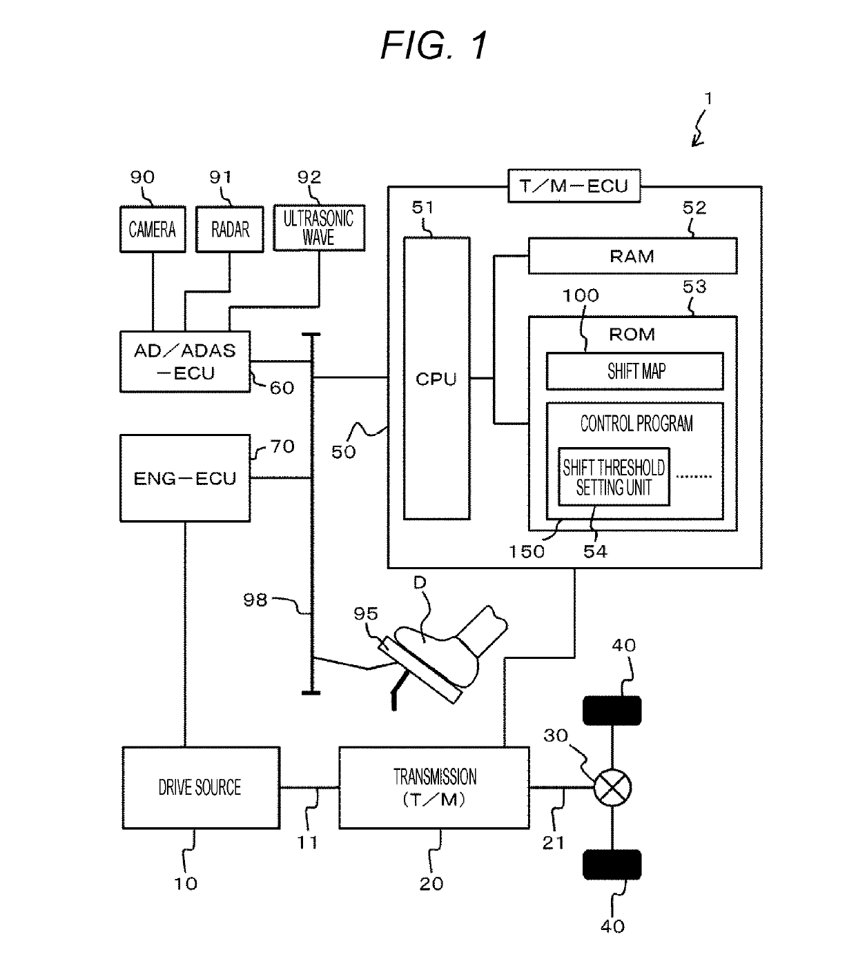
[0026]FIG. 1 is a block diagram illustrating an entire structure of the vehicle 1 according to the present invention.

[0027]As shown in FIG. 1, in the vehicle 1, a transmission (T / M) 20 is connected to an output shaft 11 of a drive source 10 and a rotation number of the output shaft 11 is shifted to a predetermined rotation number by the transmission 20.

[0028]The rotation number of the output shaft 11 shifted by the transmission 20 is transmitted to a propeller shaft 21 to be the input side of a differential gear 30 and is transmitted to left and right tires 40 and 40...


PUM


Abstract

The present invention provides a transmission control device for a vehicle capable of changing a threshold of a shift map for determining shift-up, thereby preventing occurrence of the shift-up during depression of an accelerator and preventing occurrence of a torque interruption. In a transmission control device for a vehicle 1 including a T/M-ECU 50 which automatically performs shift control for switching a plurality of shift gears of a transmission 20 for shift-up or shift-down, the T/M-ECU 50 has a shift threshold setting unit 54 which sets a shift threshold to be used for the shift control, on the basis of an operation plan or a surrounding state of the vehicle 1, and the shift threshold setting unit 54 sets the shift threshold to perform the shift control on the transmission 20 so as not to perform the shift-up of the transmission 20 during acceleration of the vehicle 1.

Description

TECHNICAL FIELD[0001]The present invention relates to a transmission control device for a vehicle.BACKGROUND ART[0002]In a vehicle including a multi-stage transmission such as an automatic transmission (AT) and an automated manual transmission (AMT), if a clutch is released according to shift-up during acceleration by depression of an accelerator, a time for which an engine torque is not transmitted to the tire side occurs (hereinafter, referred to as a torque interruption). Particularly, in the AMT that controls a single clutch on the basis of a manual transmission (MT) and performs shift-up / shift-down automatically, a long-time torque interruption occurs as compared with other transmission systems.[0003]If the torque interruption suddenly occurs during the acceleration of the vehicle, a driver who drives the vehicle receives an impact due to the sudden torque interruption (hereinafter, referred to as a torque interruption shock).[0004]Due to the occurrence of the torque interrupti...

Claims


Application Information

Patent Timeline
Patent Type & Authority Applications(United States)
IPC IPC(8): F16H59/48F16H59/46F16H61/04
CPCF16H59/46F16H61/04F16H2059/663F16H61/16F16H59/48F16H59/60F16H59/44F16H2061/0234F16H2061/163F16H2061/0227F16H61/682
Inventor TSUGE, MUNETOSHITSUTSUI, TAKASHI
Owner HITACHI ASTEMO LTD
Why Eureka
Try Eureka