Vehicle control apparatus

a technology for controlling apparatus and vehicles, applied in the direction of driver input parameters, propulsion parts, transportation and packaging, etc., can solve the problems of unsuitable warming-up, increased shock, and worse emissions (gas exhausted from the engine) of the engine, so as to improve the accuracy of controlling the rotation speed of the engine, reduce the effect of shock upon restart of the engine, and improve the accuracy of the control of the catalys

Active Publication Date: 2019-02-28
TOYOTA JIDOSHA KK
View PDF5 Cites 1 Cited by
  • Summary
  • Abstract
  • Description
  • Claims
  • Application Information

AI Technical Summary

Benefits of technology

[0015]According to the third mode of the invention, when the engine is in the second operational state, the target value of the value representing the rotational state of the engine is set to a value that causes the rotating speed of the engine to be held at a substantially constant value in the process of the shifting action. With the engine rotating speed being held at a substantially constant value, it is possible to reduce shock upon restart of the engine, and / or to cause the catalyst warming-up to be adequately performed.
[0016]According to the fourth mode of the invention, when the engine is in the second operational state, the target value of the value representing the rotational state of the engine is compensated such that the rotating speed of the engine is not made lower than the substantially constant value in the process of the shifting action, so that, even if the engine rotating speed is fluctuated, the engine rotating speed is not made lower than the target value. Thus, when the engine is stopped, the engine is avoided from being rotated in a negative direction. Further, when the engine is operated to warm up the catalyst, the catalyst warming-up can be adequately continued.
[0017]According to the fifth mode of the invention, when the power-on shift-up action of the mechanically-operated transmission mechanism is executed, it is possible to improve accuracy of control of the engine rotating speed and also improve drivability of the vehicle, depending on an operational state of the engine. That is, the above-described first mode of the invention is useful, particularly, upon execution of the power-on shift-up action of the mechanically-operated transmission mechanism in which an initiative coupling device (i.e., one of the coupling devices that causes the shifting action to be progressed) is the engaging coupling device and in which it is considered that there is a higher need for the drive force (in other words, unsatisfactory acceleration feeling is more likely to be given to a vehicle operator) when the vehicle is in the first operational state corresponding to the normal operation state.
[0018]According to the sixth mode of the invention, in the control apparatus for the vehicle equipped with the electrically-controlled transmission mechanism and the mechanically-operated transmission mechanism that are arranged in a series, when the shifting action of the mechanically-operated transmission mechanism is executed, it is possible to improve accuracy of control of the engine rotating speed and also improve drivability of the vehicle, depending on the operational state of the engine.

Problems solved by technology

If a crank angle is displaced during stop of the engine, a shock could be caused or increased when the engine is restarted.
Further, during warming-up of the catalyst, if the engine rotating speed is lowered from a target value suitable for facilitating the catalyst warming-up, the warming-up would not be performed suitably whereby emissions (gas exhausted from the engine) could be worse.
On the other hand, it is considered that there is a higher need for the drive force (in other words, unsatisfactory acceleration feeling is more likely to be given to a vehicle operator) when the vehicle is running by the drive force of the engine, than when the vehicle is running by only the drive force of the motor / generator.

Method used


Image

  • Vehicle control apparatus
  • Vehicle control apparatus
  • Vehicle control apparatus

Examples


first embodiment

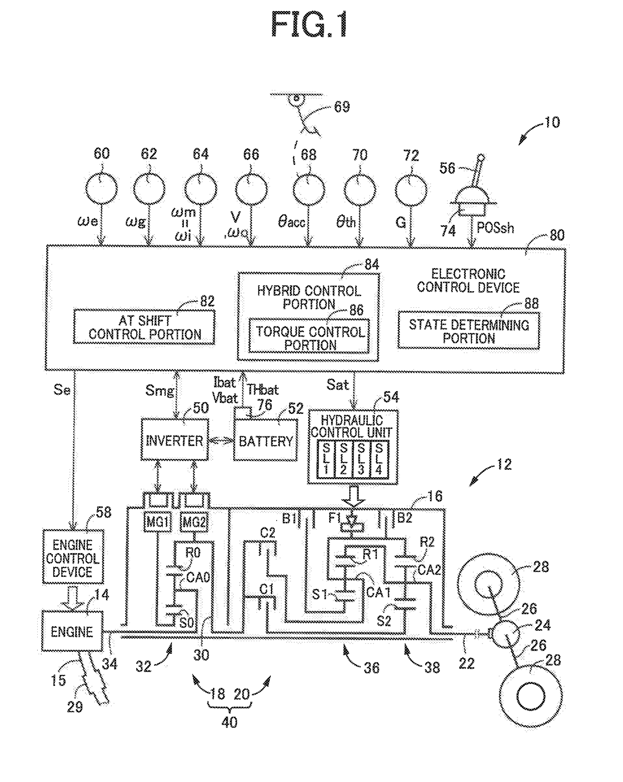
[0031]Reference is first made to FIG. 1, which is the schematic view showing an arrangement of a drive system 12 of a vehicle 10 to be controlled by a control apparatus according to the present invention, and major portions of the control apparatus to perform various controls of the vehicle 10. As shown in FIG. 1 the vehicular drive system 12 is provided with an engine 14 serving as a drive power source, an electrically-controlled continuously-variable transmission portion 18 (hereinafter referred to as “continuously-variable transmission portion 18”) connected directly or indirectly via a damper (not shown) or any other device to the engine 14, and a mechanically-operated step-variable transmission portion 20 (hereinafter referred to as “step-variable transmission portion 20) connected to an output rotary member of the continuously-variable transmission portion 18. The continuously-variable transmission portion 18 and the step-variable transmission portion 20 are disposed in series...

second embodiment

[0094]In this second embodiment, the control apparatus according to the invention is used for controlling a vehicle 100 shown in FIG. 10, which is different from the vehicle 10 in the first embodiment in which the continuously variable transmission portion 18 and the step-variable transmission portion 20 are connected in series with each other.

[0095]As shown in FIG. 10, the vehicle 100 is a hybrid vehicle including an engine 102 serving as a drive power source, a motor / generator (rotating machine) MG also serving as the drive power source, and a power transmitting system 104. The power transmitting system 104 includes a clutch K0, a torque converter 108, and an automatic transmission 110, which are disposed within a non-rotatable member in the form of a casing 106 fixed to a body of the vehicle 100, in this order of description as seen in the direction away from the engine 102. The power transmitting system 104 further includes a differential gear device 112 and axles 114. The torqu...


PUM


Abstract

A vehicle control apparatus includes: a state determining portion configured to determine whether an engine is in a first operational state corresponding to a normal operation state or a second operational state corresponding to an engine stop state in which the engine is stopped and/or a catalyst warming-up state in which the engine is operated to warm up a catalyst; and a shift control portion configured, in process of a shifting action of a transmission mechanism, to control at least an engaging pressure of an engaging coupling device as one of a plurality of coupling devices of the transmission mechanism, which is to be placed in an engaged state upon completion of the shifting action, such that the engaging pressure of the engaging coupling device is controlled to be lower when the engine is in the second operational state, than when the engine is in the first operational state.

Description

[0001]This application claims priority from Japanese Patent Application No. 2017-162816 filed on Aug. 25, 2017, the disclosure of which is herein incorporated by reference in its entirety.FIELD OF THE INVENTION[0002]The present invention relates to a control apparatus for a vehicle including a drive power source (such as engine and motor / generator) and a mechanically-operated transmission mechanism that is configured to transmit a drive force of the drive power source.BACKGROUND OF THE INVENTION[0003]There is known a control apparatus for a vehicle that includes (i) an engine serving as a drive power source, (ii) a motor / generator serving as the drive power source and (iii) a mechanically-operated transmission mechanism which constitutes a part of a power transmitting path between the drive power source and drive wheels of the vehicle and which is placed in a selected one of a plurality of gear positions with engagement of a selected one or ones of a plurality of coupling devices. A...

Claims


Application Information

Patent Timeline
Patent Type & Authority Applications(United States)
IPC IPC(8): B60W20/15B60W10/06B60W10/08B60W10/115B60W30/19
CPCB60W20/15B60W10/06B60W10/08B60W10/115B60W30/19B60W2510/1005B60W2530/12B60W2540/10B60W2710/1083B60W2710/1022B60W2710/0666B60W2710/0644B60W2710/083B60K6/445B60K6/547B60K6/365B60Y2200/92B60W20/30Y02T10/62
Inventor SUGIYAMA, KOJISASADE, SHINICHISHIIBA, KAZUYUKIMATSUBARA, TOORUYOSHIKAWA, MASATOKIMURA, TAKAHIRO
Owner TOYOTA JIDOSHA KK
Why Eureka
Try Eureka