Orthodontic shape memory band

a shape memory and orthodontic appliance technology, applied in the field of active, semi-passive or passive shape memory orthodontic appliances, can solve the problems of shortening the overall treatment time, reducing the treatment effect, so as to reduce the pain and hyalinization of patients, the treatment is advantageously simplified, and the effect of reducing the pain and hyalinization

Active Publication Date: 2019-09-19
D D
View PDF0 Cites 2 Cited by
  • Summary
  • Abstract
  • Description
  • Claims
  • Application Information

AI Technical Summary

Benefits of technology

[0027]Furthermore, the shape of the bonding zone allows the shape memory band to be fixed “directly” to the teeth. The orthodontic treatment is advantageously simplified as a result.
[0028]Finally, the treatment can be more precise, thereby making it possible to limit the pain and hyalinization phenomena in the patient.

Problems solved by technology

A passive orthodontic appliance exhibits the disadvantage of maintaining the small defects rather than correcting them.
Furthermore, if a hard piece of food bends the brace in the region between the teeth, the brace becomes active and brings about a loss of tooth alignment.
The near-standardized use of this sequence of archwires exhibits the following disadvantages:the round-section first arch wires do not allow alignment in all directions in space, particularly for corrections of torque, thus lengthening the overall treatment time;numerous orthodontist appointments are needed, particularly for changing the archwires.
These changes often cause the patients to feel pain because a sequence of archwires may generate discontinuous forces;risk that the brackets may become detached or the archwires may slip, exposing the patient's cheeks to lesions;this is a very routine repetitive action for orthodontists to perform;need to carry out time-consuming finishing bends.

Method used


Image

  • Orthodontic shape memory band
  • Orthodontic shape memory band
  • Orthodontic shape memory band

Examples


Embodiment Construction

Orthodontic Appliance

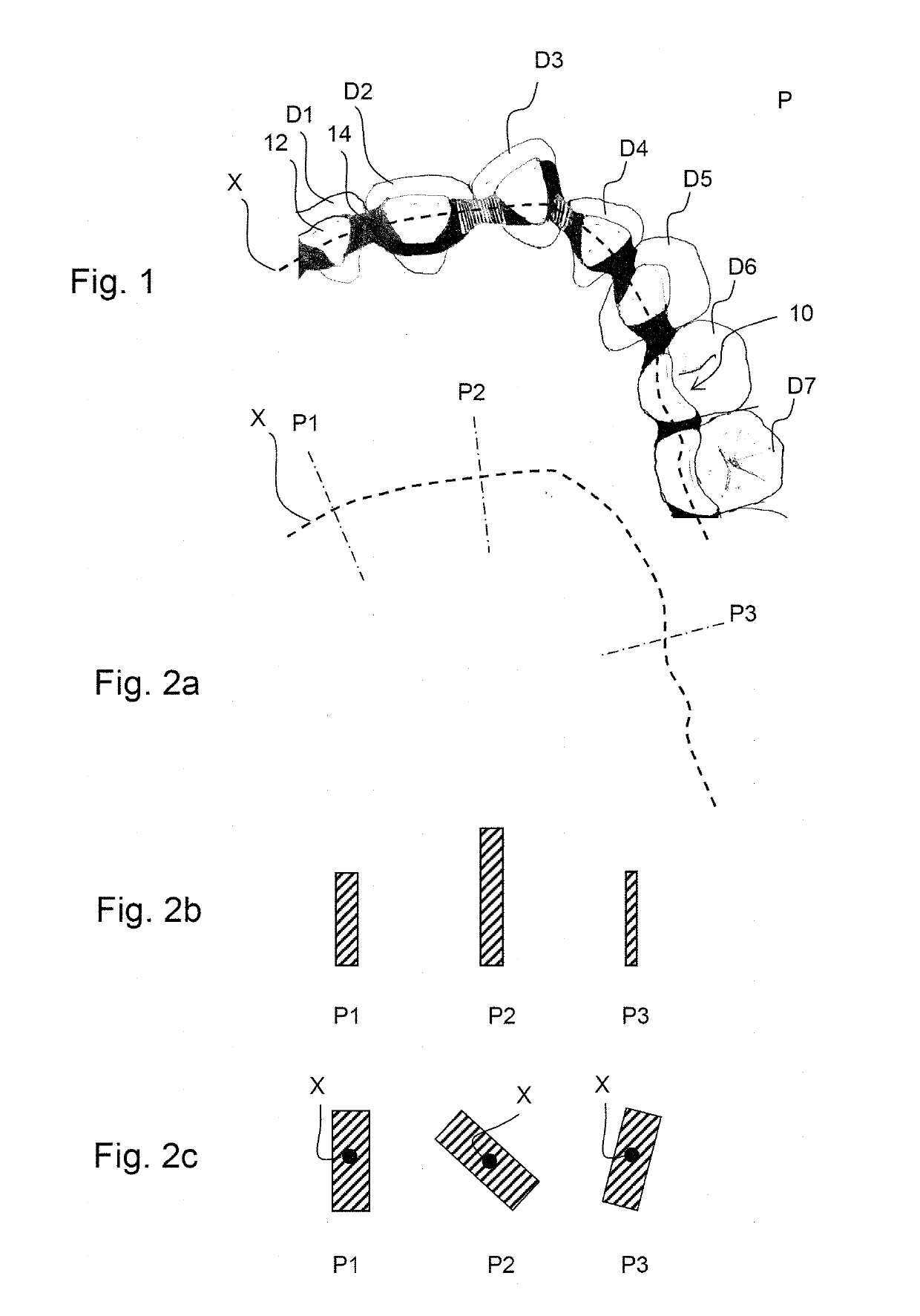
[0076]FIG. 1 depicts a first example of an orthodontic appliance according to the invention, made up of a shape memory band.

[0077]The orthodontic appliance is one piece, which means to say that it is made up of just one piece, namely the shape memory band.

[0078]The shape memory band extends along a main direction or “axis” X, depicted in broken line, preferably substantially in an overall plane P (the plane of the page in FIG. 1). The shape memory band is preferably shaped in such a way that, in the service position, the overall plane P is substantially parallel to the occlusion plane.

[0079]It is depicted in a service position in which it exerts an action to move teeth Di (i=1.7) (hereinafter referred to generically as “D”), relative to one another.

[0080]For preference, as depicted in FIGS. 5a to 5c, at least one, and preferably each, of the ends 10a and 10b of the shape memory hand exhibits rounded shapes, preferably without any sharp edge corners. Thus, in the...


PUM


Abstract

A method for producing a shape memory band of an orthodontic appliance. The shape memory band is one piece, has a cross section that can vary according to the longitudinal position of said cross section, and includes a bonding zone configured so as to exhibit a shape substantially identical to that of a tooth. The method includes: determining an orthodontic treatment suitable for treating the teeth, determining a set of forces to be exerted locally on the teeth in order to obtain the orthodontic treatment and the shape of the surface of the teeth to which bonding zones of the shape memory band are to be bonded, and producing the shape memory band. The local cross section of the shape memory band is determined according to the forces and in such a way as to define bonding zones substantially identical to the surfaces of the teeth.

Description

TECHNICAL FIELD[0001]The invention relates to an active, semi-passive or passive shape memory orthodontic appliance and to a method for designing such an appliance.PRIOR ART[0002]A passive orthodontic appliance or “retainer” is an appliance intended to hold a patient's teeth in position, usually after an active orthodontic treatment.[0003]A passive orthodontic appliance exhibits the disadvantage of maintaining the small defects rather than correcting them. Furthermore, if a hard piece of food bends the brace in the region between the teeth, the brace becomes active and brings about a loss of tooth alignment.[0004]An active orthodontic appliance is an appliance intended to move the malpositioned teeth of a patient.[0005]The most widespread orthodontic appliance, the “multi-fixings” appliance, is made up of “brackets” bonded to the teeth and into which an archwire is introduced.[0006]The action of multi-fixings active orthodontic appliances results in a set of forces exerted on the te...

Claims


Application Information

Patent Timeline
Patent Type & Authority Applications(United States)
IPC IPC(8): A61C7/20A61C7/28
CPCA61C2201/007A61C7/20A61C7/28A61C7/12A61C5/007A61C7/08
Inventor BENAROUCH, DANMAJBRUCH, DELPHINE
Owner D D
Why Eureka
Try Eureka