Orthodontic appliance for distalization and/or space closure

a technology for distalization and space closure, which is applied in the field of orthodontic appliances for distalization and/or space closure, can solve the problems of inability to control the moments in all three planes of space, inability to precisely behave, and inability to generate undesirable moments, etc., to achieve excellent anchorage control, shorten the duration of treatment, and simplify the effect of treatmen

Active Publication Date: 2017-03-23
PATEL VISHNU JAGDISHBHAI
View PDF30 Cites 3 Cited by
  • Summary
  • Abstract
  • Description
  • Claims
  • Application Information

AI Technical Summary

Benefits of technology

[0013]As the disclosed orthodontic appliances are placed in lingual region of the jaw in orthodontic treatment, the orthodontic appliances, unlike other appliances, are not visible. Hence, the disclosed orthodontic appliances provide an option of aesthetic appeal in orthodontic treatment. Further, as complex wire bending is not required with use of disclosed orthodontic appliances, the orthodontic treatment is simplified. As the disclosed orthodontic appliances simulate the center of resistance using components that can deliver appropriate force unlike frictionless (or loop) mechanisms and friction (or sliding) mechanisms, the duration of treatment can be shortened.
[0014]Anchorage losses were observed in continuous arch wire sliding mechanisms even though force is not applied from the posterior dentition of a jaw. In response to the retraction force from micro-implants, an arch wire extending distal from the anterior segment of the jaw generates mesial root uprighting moments in the posterior segment of the jaw. This tilt in association with the built in tip and anterior component of force takes the posterior anchorage segment bodily forward. By avoiding continuity of the anterior and posterior arch and holding the posterior segment in place with the palatal micro-implants, excellent anchorage control can be achieved. Retraction force is applied between two isolated segments, thus there is no sliding of the wire at all during space closure. Thus unknown components of sliding resistance in the form of friction and binding are avoided.
[0015]The disclosed orthodontic appliances also reduce armamentarium for multiple applications in orthodontic treatment. The disclosed orthodontic appliances simulate the center of resistance in controlled extraction space closure not only in the anterio-posterior plane, but in all three planes of space for various anchorage demands. Further, with the disclosed orthodontic appliances simulating the center of resistance, distal movement of either individual tooth, teeth segments (anterior teeth i.e. central incisors, lateral incisors and canines, posterior teeth i.e. premolars and molars segments), unilateral or bilateral segments of dental arch, and en masse dentition is made possible.

Problems solved by technology

Space closure and distalization are important and skill demanding issues in orthodontics.
Most of those moments that are generated are undesirable in majority of clinical cases.
In friction (sliding) mechanisms, variable sliding resistance and longer duration to reach working wires for retraction make the techniques statically indeterminate and unpredictable for various movements.
These are neither capable of controlling the moments in all three planes of space, nor rigid enough to behave exactly as presumed to do so.
Such power arms are too bulky to be tolerated by the patients.
However, anchorage loss has been documented in continuous arch wire biomechanics because of the mesial root moments generated on either side of posterior segments in response to the retraction force on anterior segment, which is applied away (occlusal) from the center of resistance of the anterior segment.
As the center of resistance of the anterior segment in the alveolus between lateral incisor and canine root each side is not easily accessible and the rigidity of the vestibular extended wire is questionable, cantilever mechanisms fail to maintain three dimensional controlled space closure.
Though SAS performs well for this objective, better than the mini or micro implants, two additional surgeries performed by oral surgeon and associated costs are the main drawbacks.

Method used


Image

  • Orthodontic appliance for distalization and/or space closure
  • Orthodontic appliance for distalization and/or space closure
  • Orthodontic appliance for distalization and/or space closure

Examples


Embodiment Construction

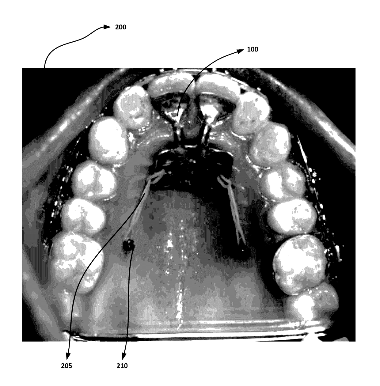
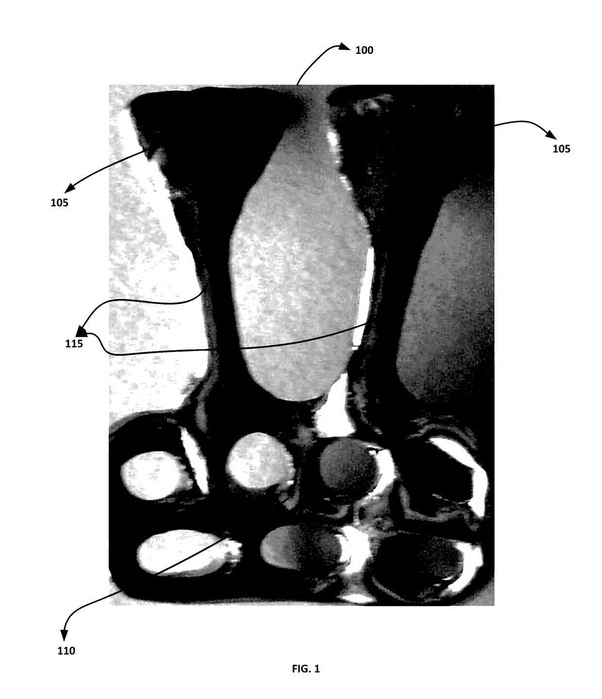
[0031]FIG. 1 illustrates an anterior orthodontic appliance embodiment 100, according to the invention. As shown in the figure, the anterior orthodontic appliance 100 has two bonding pads 105, two vertical connectors 115 and a netted structure 110. The two vertical connectors 115 connect the two bonding pads 105 and netted structure 110. The vertical connectors 115 are in lingual and apical direction. The illustrated netted structure 110 is formed of holes for passing or engaging force delivering components. However, the netted structure 110 can be comprised of at least one of holes, hooks and stops for passing or engaging force delivering components. The use of the anterior orthodontic appliance embodiment 100 is described with reference to FIGS. 2, 2A and 2B.

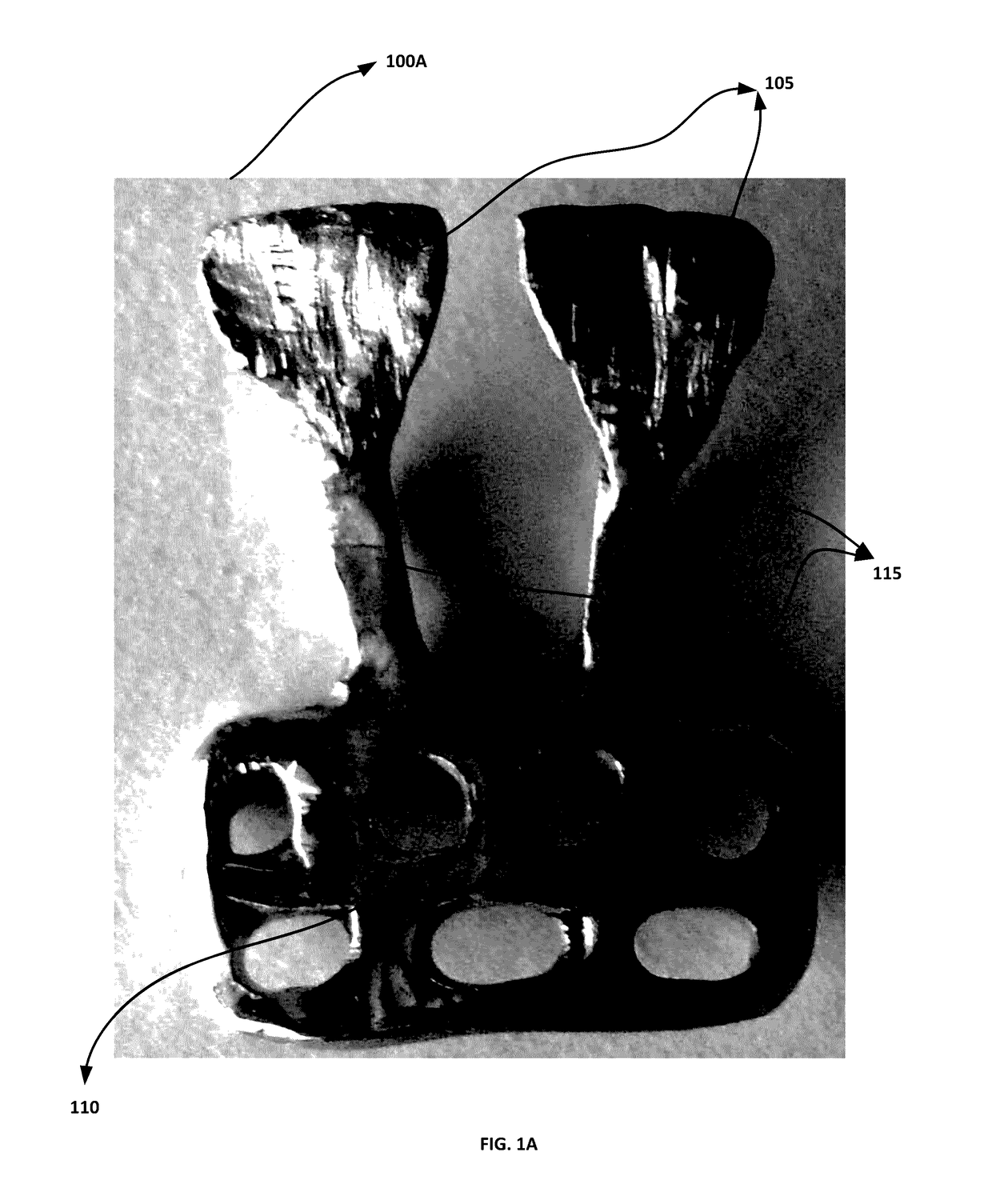
[0032]FIG. 1A illustrates reverse view of the anterior orthodontic appliance embodiment 100A, according to the invention. The illustrated side of bonding pads 105 are attached to lingual side of the teeth in the anterior region...


PUM


Abstract

The invention relates to orthodontic appliances that simulate the center of resistance in orthodontic treatment. The orthodontic appliance includes at least one bonding pad for attaching said appliance to a corresponding lingual side of a tooth and a netted structure extending in a mesial-distal direction substantially below the at least one bonding pad. The netted structure engages or passes components for delivering force in orthodontic treatment. With aid of the force delivering components engaged or passed in the netted structure, a dentist or a clinician can advantageously simulate the center of resistance in a dentition or a tooth in orthodontic treatment for space closure and/or distalization.

Description

CROSS REFERENCE TO RELATED APPLICATION[0001]This application is a non-provisional application of the provisional application no. 3562 / MUM / 2015, filed Sep. 18, 2015 with Intellectual Property Office, Mumbai, India, the contents of which are incorporated herein in their entirety by reference as if set forth in full below.COPYRIGHT NOTICE[0002]A portion of the disclosure of this patent application contains material that is subject to copyright protection. The copyright owner has no objection to the facsimile reproduction by anyone of the patent application or the patent disclosure, as it appears in the Patent and Trademark Office patent file or records, but otherwise reserves all copyright rights whatsoever.BACKGROUND OF THE INVENTION[0003]Space closure and distalization are important and skill demanding issues in orthodontics. The mechanics for space closure have evolved through many trials and errors. The contemporary space closure mechanisms that are widely practiced are frictionles...

Claims


Application Information

Patent Timeline
Patent Type & Authority Applications(United States)
IPC IPC(8): A61C7/14A61C7/16A61C8/00
CPCA61C7/145A61C7/16A61C8/0096A61C7/10
Inventor PATEL, VISHNU JAGDISHBHAI
Owner PATEL VISHNU JAGDISHBHAI
Why Eureka
Try Eureka