Electronic apparatus having heat dissipation system

a technology of heat dissipation system and electronic equipment, which is applied in the direction of electrical apparatus construction details, television systems, instruments, etc., can solve the problems of affecting the efficiency of cooling heat sources, increasing lens aberration in photographed images, and affecting the use of users. , to achieve the effect of reducing the number of components and efficiently cooling heat sources

Active Publication Date: 2019-09-19
CANON KK
View PDF7 Cites 6 Cited by
  • Summary
  • Abstract
  • Description
  • Claims
  • Application Information

AI Technical Summary

Benefits of technology

[0011]The present invention provides an electronic apparatus that is capable of cooling heat sources efficiently by taking in outside air through intake ports effectively while reducing the number of components.

Problems solved by technology

In such an image pickup apparatus, heat generated by the heat sources mentioned above may affect electric elements implemented in a substrate and may cause an obstacle of the substrate.
Moreover, the heat sources may make an exterior of the image pickup apparatus hot, which may give displeasure to a user who holds the image pickup apparatus.
As a result, the shape of the image pickup lens unit may become asymmetrical, which may give a bad influence, such as increase of lens aberration in a photographed image.
Because when a single fan is provided in the apparatus that has the plurality of intake ports, difference in ventilation resistance occurs in the air flow paths, which disturbs efficient cooling of the heat sources.
However, when a fan is provided to each of the plurality of intake ports, the image pickup apparatus is enlarged and the cost increases because the number of components increases.

Method used


Image

  • Electronic apparatus having heat dissipation system
  • Electronic apparatus having heat dissipation system
  • Electronic apparatus having heat dissipation system

Examples


first embodiment

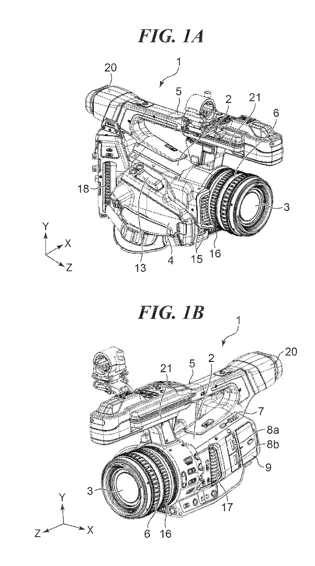
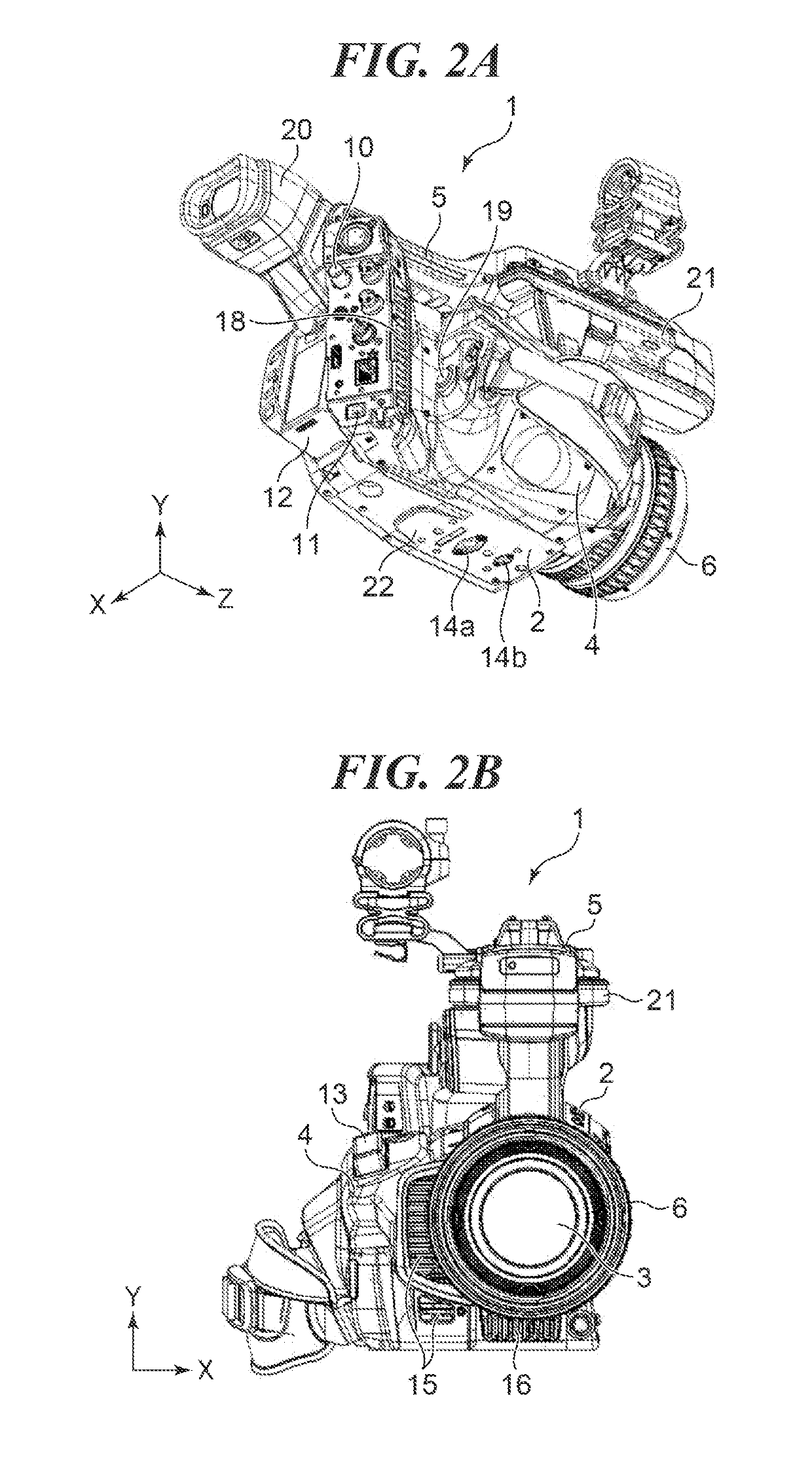
[0036]FIG. 1A, FIG. 1B, FIG. 2A, and FIG. 2B are views for describing an example of an image pickup apparatus that is an electronic apparatus according to the present invention. It should be noted that an X-axis is defined in a left-and-right direction (a left side is “+” and a right side is “−”) viewed from a user who uses the image pickup apparatus, a Y-axis is defined in a vertical direction (an upper side is “+” and a bottom side is “−”), and a Z-axis is defined in a front-and-rear direction (a front side is “+” and a rear side is “−”) as shown in the drawings. FIG. 1A is a perspective view viewed from a front-right side, and FIG. 1B is a perspective view viewed from a front-left side. Moreover, FIG. 2A is a perspective view viewed from a rear-bottom side, and FIG. 2B is a front view.

[0037]For example, the illustrated image pickup apparatus is a digital video camera (hereinafter referred to as a camera, simply) 1 that has a camera body 2, an image pickup lens unit (hereinafter r...

second embodiment

[0130]FIG. 19A and FIG. 19B are exploded perspective views for describing an example of a heat dissipation mechanism of the camera according to the present invention. FIG. 19A and FIG. 19B are the exploded perspective views showing a third duct 83, an elastic member 84 having an opening 82, and a second exhaust duct 85 viewed in the X-direction and the Y-direction, respectively.

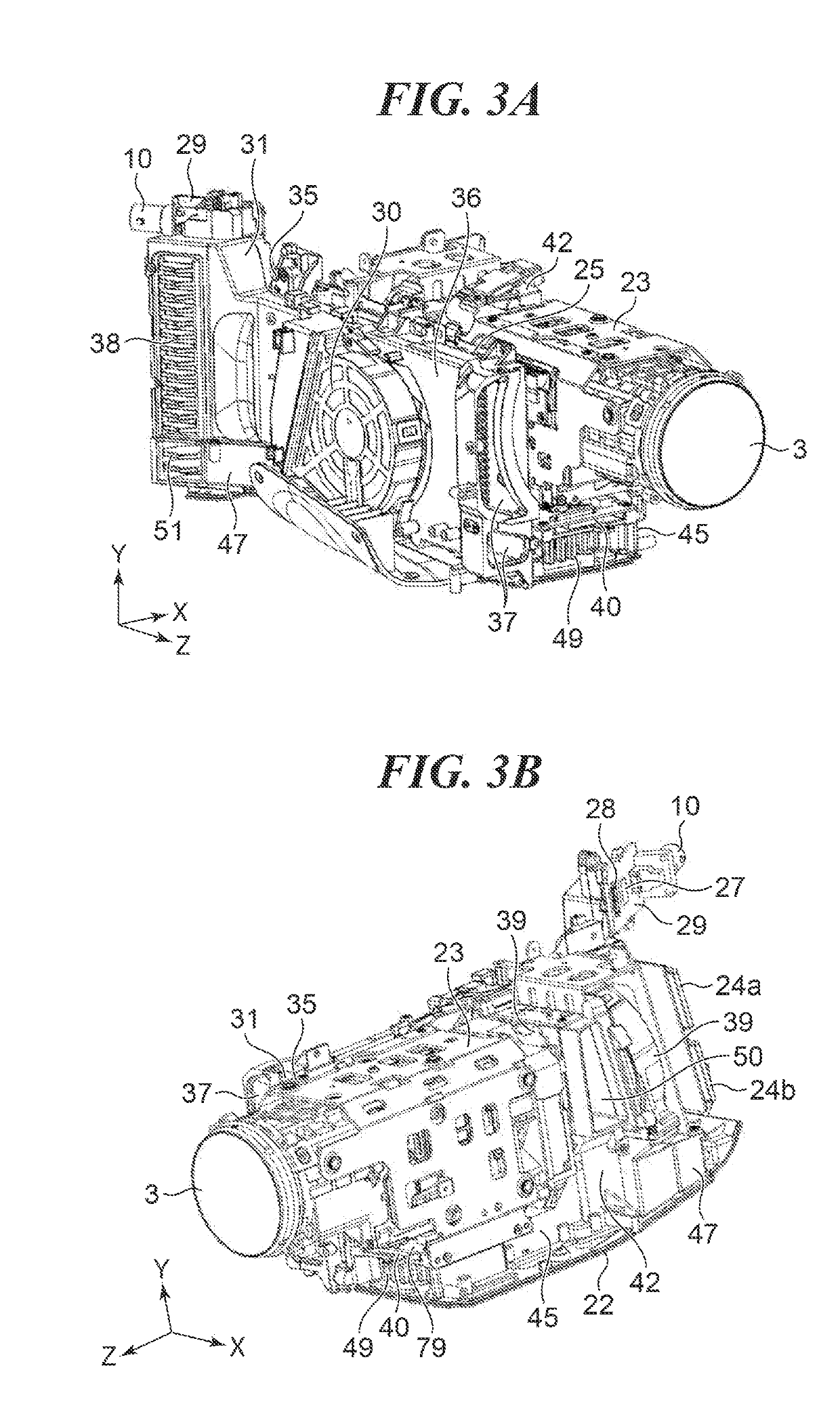
[0131]A heat generation amount of the main control substrate 25 (FIG. 3A) is more than a sum of a heat generation amount of the codec substrate 79 (FIG. 3B) and a heat generation amount of the sensor substrate 39 (FIG. 3B). Moreover, the ventilation resistance of the first duct 31 is smaller than the ventilation resistance of the second duct 42. And, the first centrifugal fan 30 and the second centrifugal fan 41 are driven at an almost identical rotation frequency in order to avoid a beats phenomenon of the fans.

[0132]As a result, the exhaust wind exhausted from the first exhaust port 38 exhibits a lower flow...


PUM


Abstract

An electronic apparatus that is capable of cooling heat sources efficiently by taking in outside air through intake ports effectively while reducing the number of components. The electronic apparatus obtains an image signal corresponding to an optical image formed through an image pickup lens. A first heat generating element is implemented in a first substrate. A second heat generating element is implemented in a second substrate. A first duct is connected to the first heat generating element at a position nearer to an exhaust port formed in a housing of the electronic apparatus than a first blower that sends air to the first duct. A second duct is connected to the second heat generating element at a position nearer to the exhaust port than a second blower that sends air to the second duct.

Description

BACKGROUND OF THE INVENTIONField of the Invention[0001]The present invention relates to an electronic apparatus, and in particular, relates to the electronic apparatus having a heat dissipation system with a fan.Description of the Related Art[0002]Generally, an image pickup apparatus, such as a video camera that is one of electronic apparatuses, has heat sources, such as a main process substrate and a sensor substrate. Furthermore, the image pickup apparatus like a video camera has an external output terminal for outputting a video signal obtained by photographing to an external monitor etc.[0003]In such an image pickup apparatus, heat generated by the heat sources mentioned above may affect electric elements implemented in a substrate and may cause an obstacle of the substrate. Moreover, the heat sources may make an exterior of the image pickup apparatus hot, which may give displeasure to a user who holds the image pickup apparatus.[0004]In addition, when an image pickup lens unit ...

Claims


Application Information

Patent Timeline
Patent Type & Authority Applications(United States)
IPC IPC(8): G03B17/55H05K7/20H04N5/225
CPCH04N5/22521G03B17/55H05K7/20172H04N5/2252H05K7/20145H04N23/52H04N23/51
Inventor MANO, HAYATOOYAMA, KAZUNA
Owner CANON KK
Why Eureka
Try Eureka