Repeaters with fast transitions from low-power standby to low-frequency signal transmission

Active Publication Date: 2019-09-19
PERICOM SEMICON
View PDF2 Cites 21 Cited by
  • Summary
  • Abstract
  • Description
  • Claims
  • Application Information

AI Technical Summary

Benefits of technology

[0005]According to a first class of implementations, a circuit includes a power supply node and an internal circuit node. The circuit also includes voltage-mode circuitry including a buffer and a switch connected between an output node of the buffer and the power supply node, the voltage-mode circuitry configurable based in part on a first state of a signal detector to provide a low frequency signal conf

Problems solved by technology

The rapidly growing throughput speeds for various I/O (input/output) standards is causing

Method used


Image

  • Repeaters with fast transitions from low-power standby to low-frequency signal transmission
  • Repeaters with fast transitions from low-power standby to low-frequency signal transmission
  • Repeaters with fast transitions from low-power standby to low-frequency signal transmission

Examples


Embodiment Construction

[0017]Reference will now be made in detail to specific implementations. Examples of these implementations are illustrated in the accompanying drawings. These examples are provided for illustrative purposes and are not intended to limit the scope of this disclosure. Rather, alternatives, modifications, and equivalents of the described implementations are included within the scope of this disclosure as defined by the appended claims. In addition, specific details may be provided in order to promote a thorough understanding of the described implementations. Some implementations within the scope of this disclosure may be practiced without some or all of these details. Further, well known features may not have been described in detail for the sake of clarity.

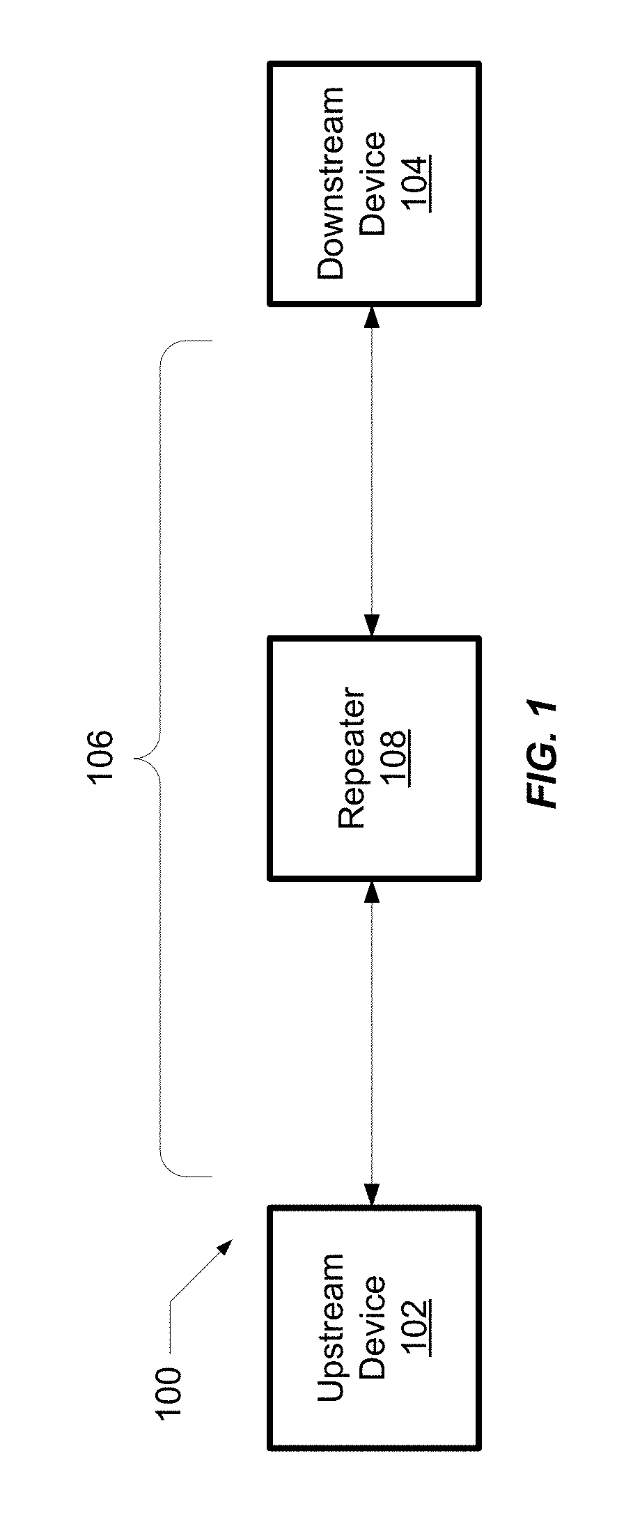
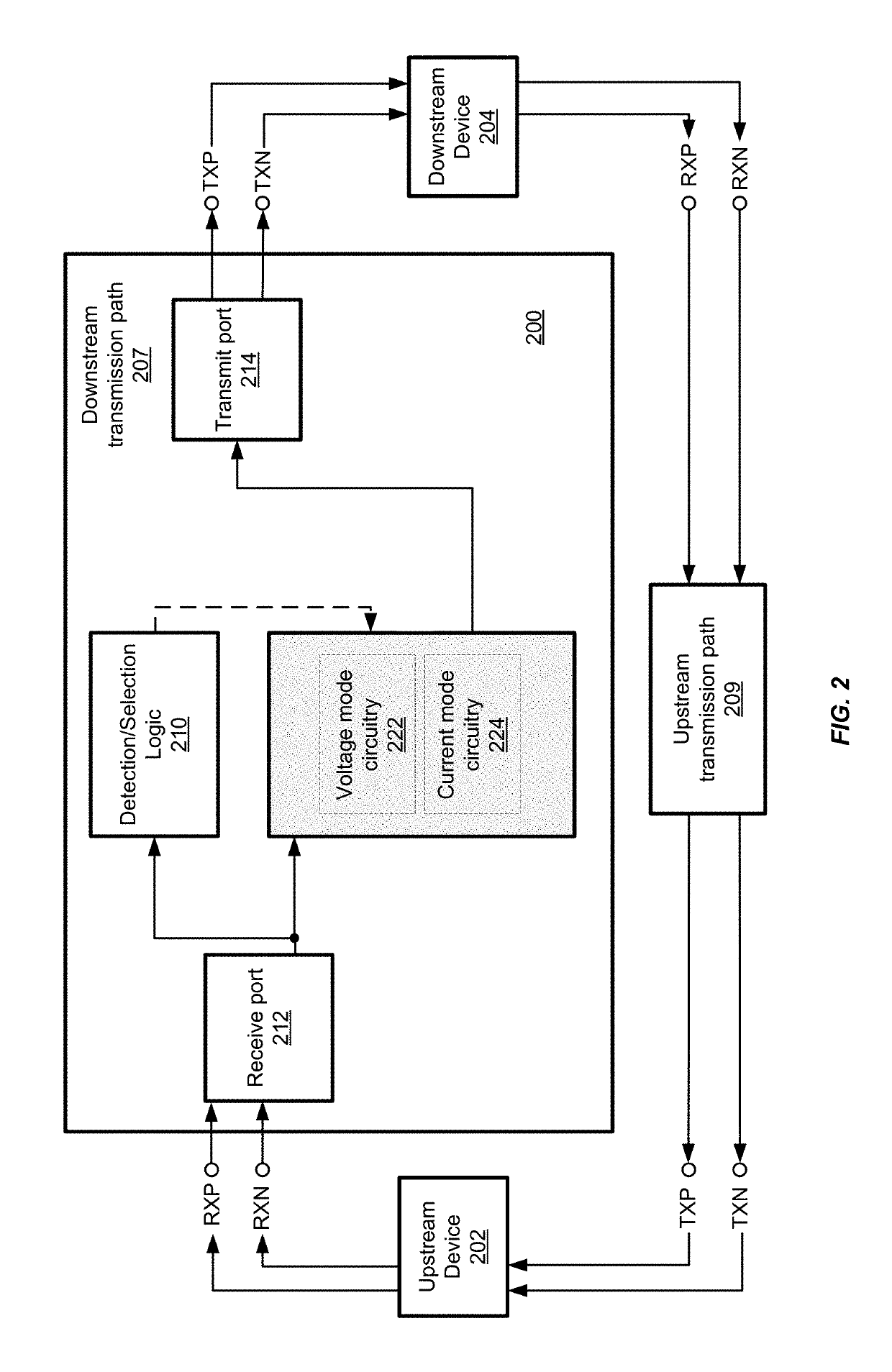
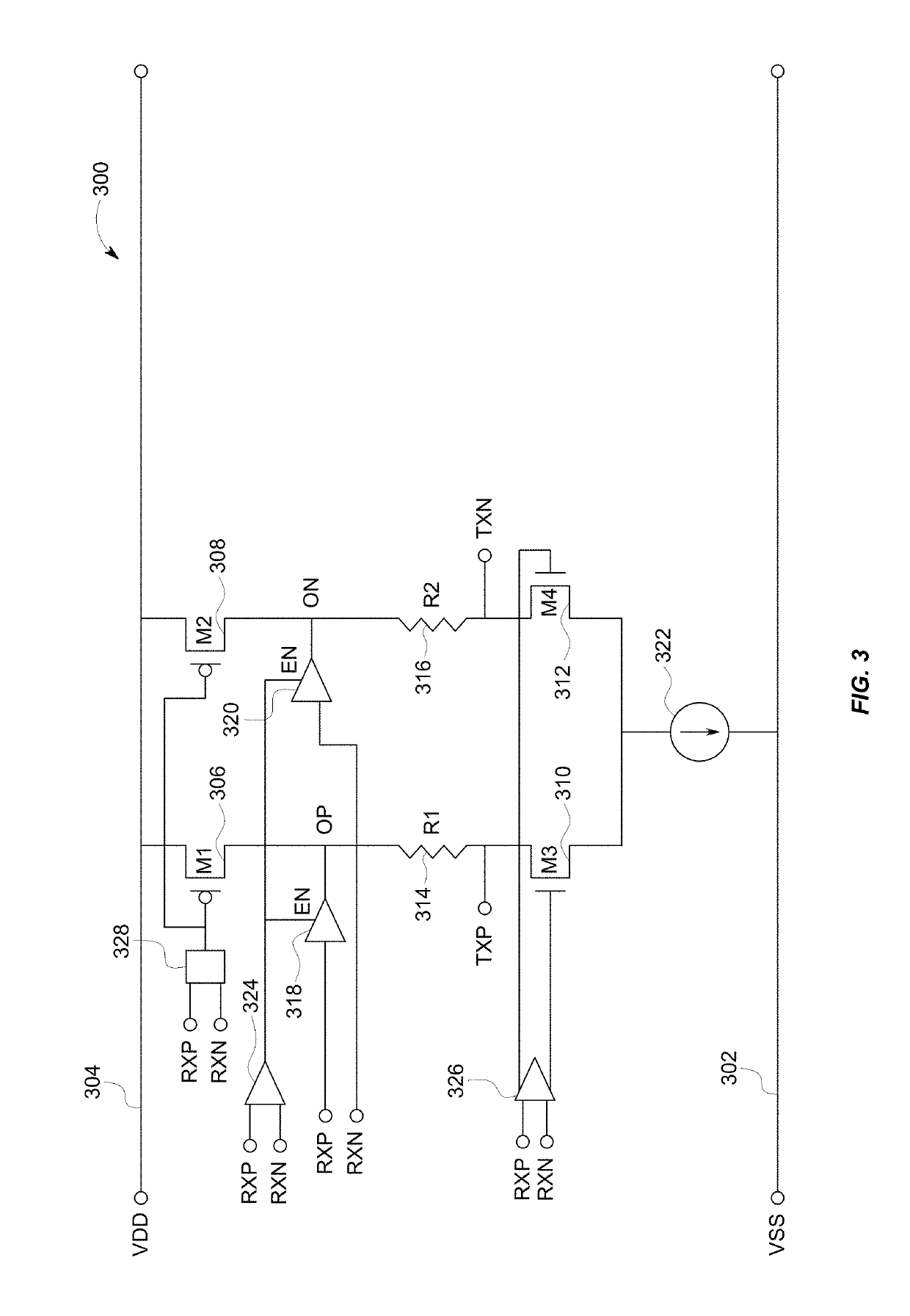
[0018]Repeaters for transmitting low-frequency signals and high-frequency signals in accordance with serial data protocols are described. Repeaters enabled by the present disclosure are designed to facilitate fast transitions from lo...


PUM


Abstract

Repeaters are described that operate to rapidly transition from low-power standby states to a low frequency signal transmission state. Bandwidth for high-frequency signal transmission is preserved.

Description

BACKGROUND[0001]With the rapid increase in the volume of data consumption on mobile devices, the need for high bandwidth, compact, and power conserving signal conditioning circuits is growing. To support the high data volumes, signal conditioning circuits must satisfy stringent performance specifications, such as fast setup when exiting power down modes, low jitter, and low standby bias current. The rapidly growing throughput speeds for various I / O (input / output) standards is causing signal conditioning circuit design specifications to become more demanding and complicated.[0002]The signal conditioning performed by a repeater is a critical task in serial communication systems. Repeaters are used in a wide range of applications, including redrivers and retimers. One objective of repeaters is to regenerate signals to boost the signal quality of high-speed interfaces. Repeaters are a key technology for addressing the signal integrity challenges that higher data rates introduce across e...

Claims


Application Information

Patent Timeline
IPC IPC(8): H04B3/36H04L25/24H03F3/45H03F1/02
CPCH03F1/0205H04B3/36H04L25/24H03F3/45179H03F2203/45026H03L5/00H03F3/45H04B1/16H03F3/45183H03F2203/45566H04L25/0272H04L25/12H04B17/401
Inventor WANG, JIN-SHENGCHOY, KWOK WINGYU, KAI HUNG
Owner PERICOM SEMICON
Why Eureka
Try Eureka