Structure of microspeaker

a micro-speaker and structure technology, applied in the direction of transducer details, electrical transducers, earpiece/earphone attachments, etc., can solve the problems of high difficulty of process, high degree of difficulty of process, and easy deviation of coupled portions, so as to reduce deviation and improve production efficiency , the effect of improving bass performan

Active Publication Date: 2019-09-19
BUJEON
View PDF12 Cites 6 Cited by
  • Summary
  • Abstract
  • Description
  • Claims
  • Application Information

AI Technical Summary

Benefits of technology

[0007]An object of the present invention is to provide the structure of a microspeaker, in which production efficiency may be improved through a reduction in deviation and bass performance may be also improved by disposing a duct and a reactive element in a speaker driver and sound quality may be improved by controlling mid-frequency characteristics.

Problems solved by technology

However, in an actual process, a deviation may occur easily in a coupled portion.
Furthermore, it is difficult to perform complete sealing, and thus the process is a process having a high degree of difficulty.

Method used


Image

  • Structure of microspeaker
  • Structure of microspeaker
  • Structure of microspeaker

Examples


second embodiment

[0044]Next, the structure of a microspeaker according to the present invention will be described.

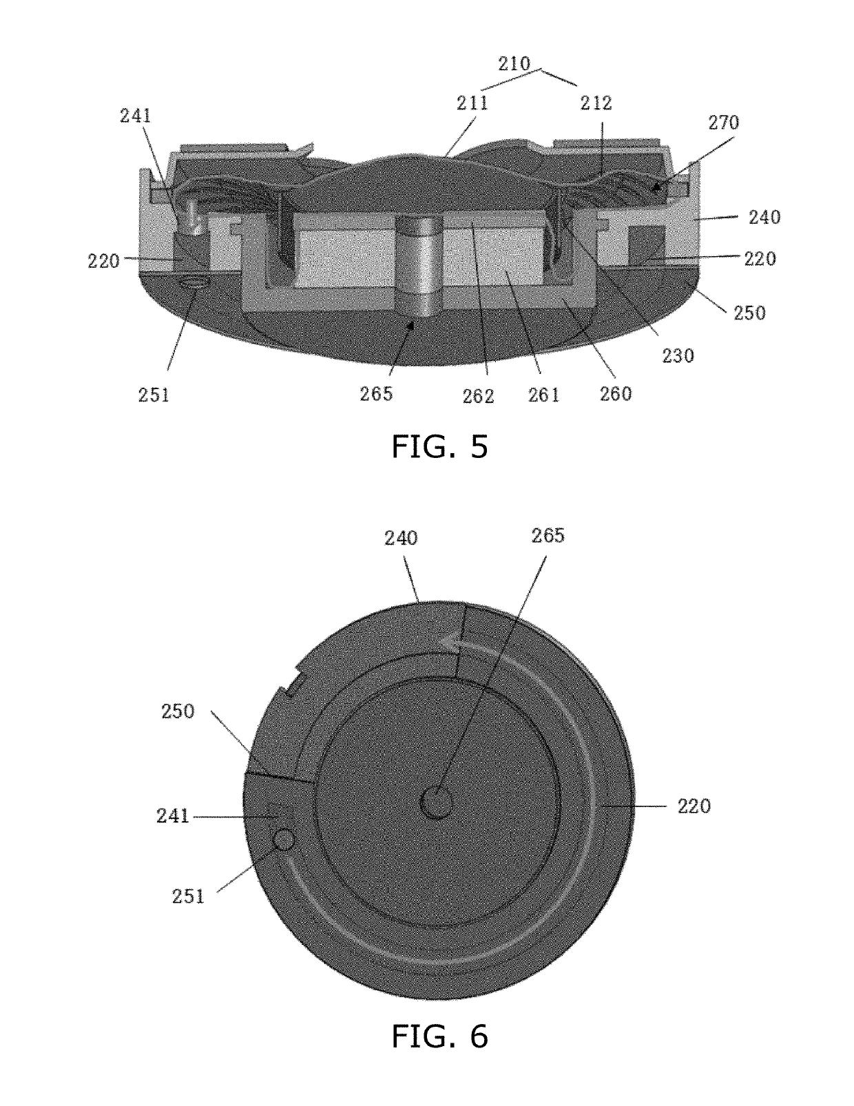
[0045]FIG. 5 is a view showing the structure of the microspeaker according to the second embodiment of the present invention, FIG. 6 is a bottom view showing the structure of the microspeaker according to the second embodiment of the present invention, and FIG. 7 is a bottom perspective view showing the structure of the microspeaker according to the second embodiment of the present invention.

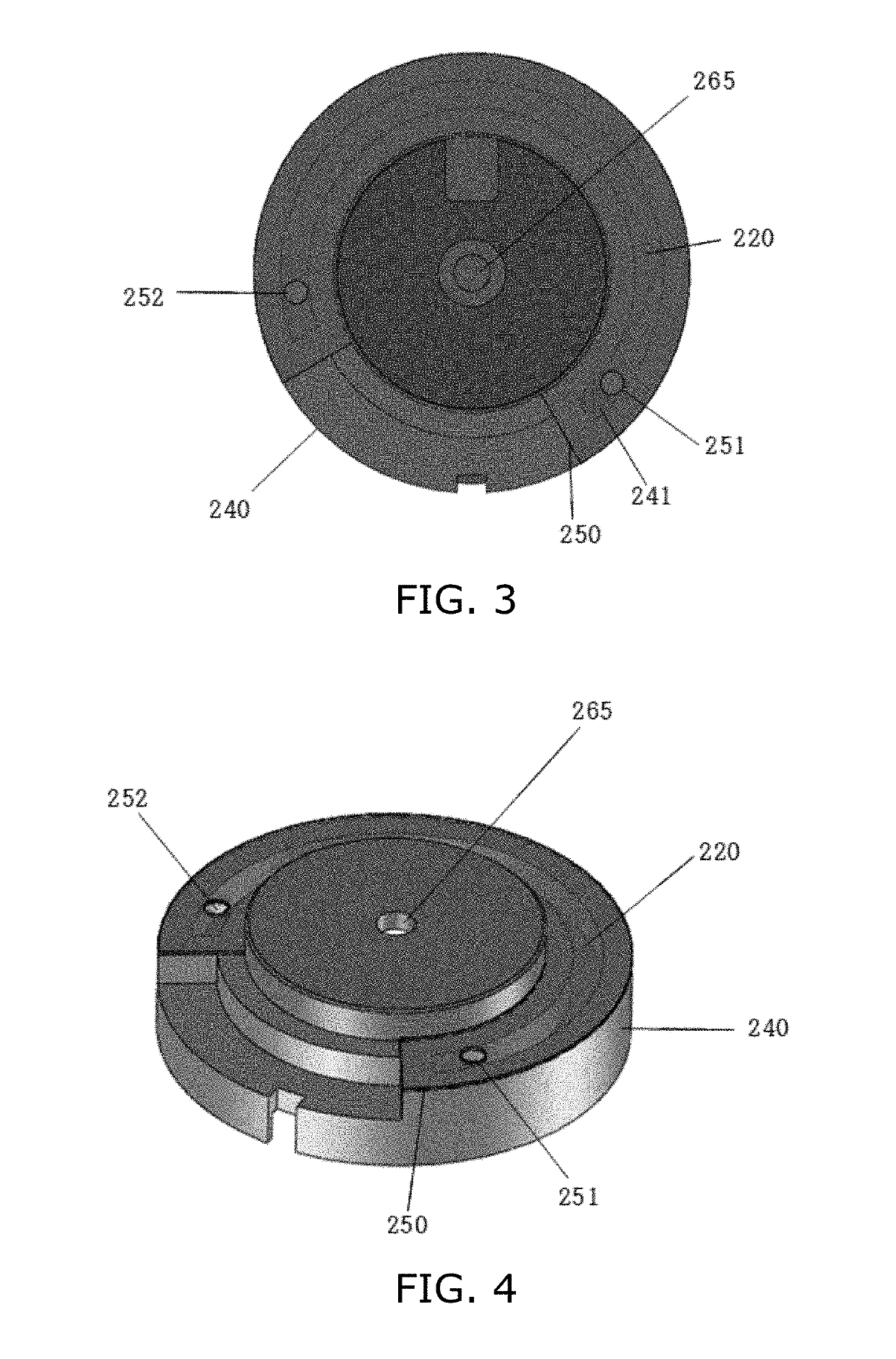
[0046]As shown in FIGS. 5 to 7, according to the second embodiment of the present invention, there is provided the structure of a microspeaker, including: a frame 240 configured to have an internal space, a magnetic field part disposed inside the frame 240 and configured to form an air gap along with the frame 240, and a diaphragm 210 configured to vibrate vertically in response to the operation of a voice coil 230 located inside the air gap, wherein a duct 220 configured to guide an air flow is form...

first embodiment

[0048]As shown in the drawings, air enters the duct 220 from the internal chamber 270 under the diaphragm 210 through a frame hole 241, the air flow of the air is guided through the duct 220 in the arrow direction shown in FIG. 6, and then the air is discharged through the other open end of the duct 220. Other configurations and effects are the same as those of the first embodiment, and thus detailed descriptions thereof will be omitted.

[0049]Meanwhile, FIG. 8 shows the comparison between the characteristics of a microspeaker in which only a first or second reactive control part is present in a speaker frame 240 and a duct is not present in a housing and the characteristics of the microspeaker according to the present invention in which the reactive control parts according to the present invention are included and the duct is formed in the frame. As shown in FIG. 8 (the units of measurement on the x axis: Hz; and the units of measurement on the y axis: dB), it can be seen that in th...


PUM


Abstract

Disclosed herein is the structure of a microspeaker. The structure of the microspeaker includes: a frame configured to have an internal space, a magnetic field part disposed inside the frame and configured to form an air gap along with the frame, and a diaphragm configured to vibrate vertically in response to the operation of a voice coil located inside the air gap. A duct configured to guide an air flow is formed in the circumferential direction of the frame. At least one frame hole is formed such that air enters the duct from the internal chamber of the frame. At least one duct sound outlet is formed such that air having entered the duct is discharged to the outside through the guide path of the duct.

Description

CROSS-REFERENCE TO RELATED APPLICATION[0001]This application claims the benefit of Korean Patent Application No. 10-2018-0030334 filed on Mar. 15, 2018, which is hereby incorporated by reference herein in its entirety.BACKGROUND1. Technical Field[0002]The present invention relates generally to the structure of a microspeaker, and more specifically to the structure of a microspeaker, in which bass performance may be improved by forming a duct in a frame.2. Description of the Related Art[0003]In general, microspeakers are widely used to convert electric signals into sound signals in portable electronic devices, such as smartphones, portable communication terminals, notebook computers, MP3 players, etc. Such a microspeaker (an earphone) includes a frame configured to have an internal space of a predetermined size therein, a magnetic circuit system accommodated inside the internal space and configured to form a gap, a diaphragm mounted over the frame, and a voice coil attached under the...

Claims


Application Information

Patent Timeline
Patent Type & Authority Applications(United States)
IPC IPC(8): H04R1/22H04R1/02H04R9/06
CPCH04R1/22H04R9/06H04R1/02H04R1/2826H04R2400/11H04R1/1075
Inventor LEE, SEUNGCHEOL
Owner BUJEON
Why Eureka
Try Eureka