Flexible crowd seating

a crowd seating and flexible technology, applied in the seating furniture, stools,ambulance services, etc., can solve the problems of spectators falling from height over low barriers, seat backs etc. falling forward and falling on top of other, and not completely eliminating standing within the seating area, so as to reduce the total height of the tiers and save construction costs

a crowd seating and flexible technology, applied in the seating furniture, stools,ambulance services, etc., can solve the problems of spectators falling from height over low barriers, seat backs etc. falling forward and falling on top of other, and not completely eliminating standing within the seating area, so as to reduce the total height of the tiers and save construction costs

US20190298063A1Active Publication Date: 2019-10-03CUNNAH MICHAEL +1

Image

  • Flexible crowd seating
  • Flexible crowd seating
  • Flexible crowd seating

Examples


Embodiment Construction

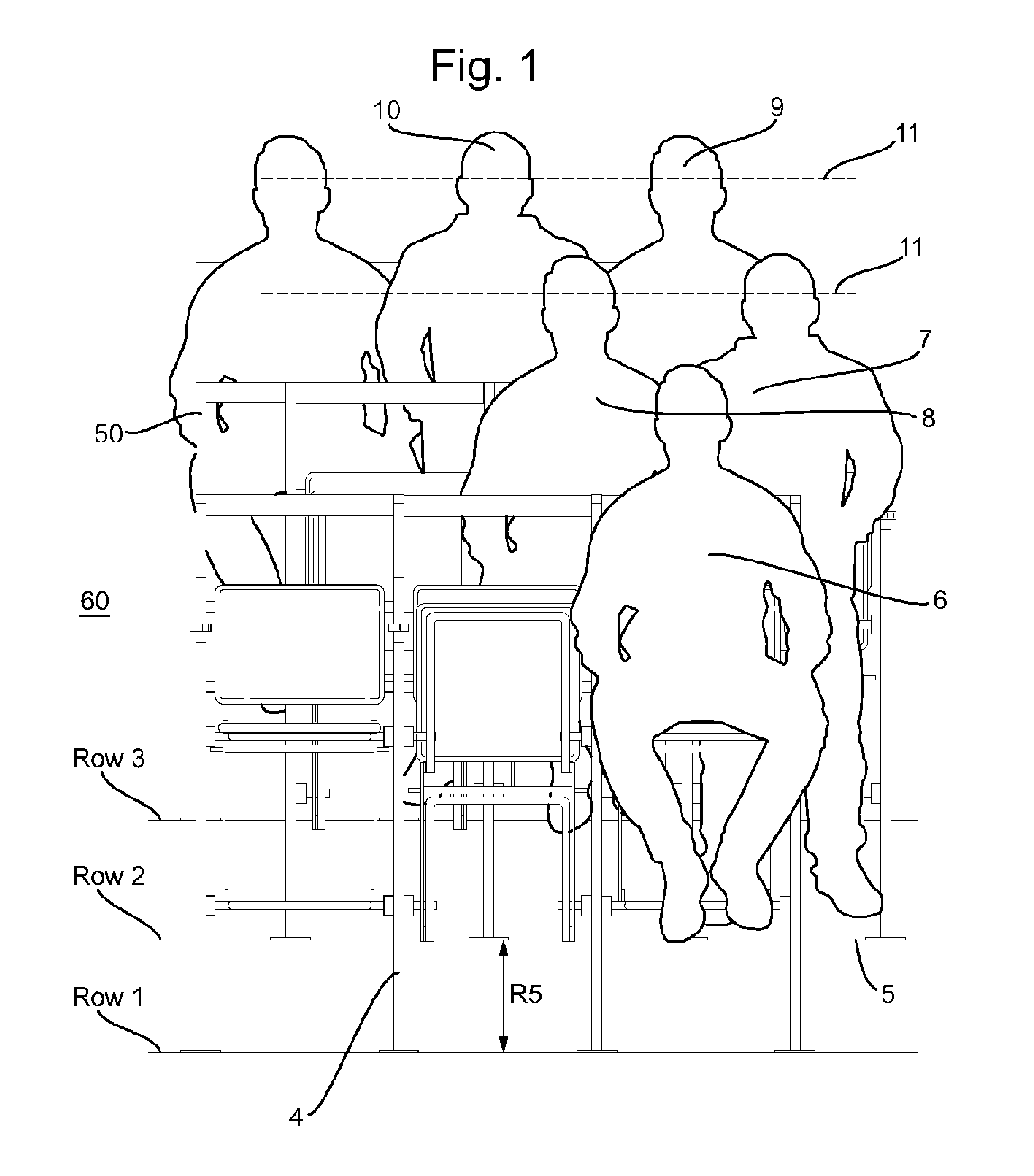
[0047]In FIG. 1 shows a number of exemplary seat units 4 according to the invention mounted on the flat steps 5 of Rows 1, 2 and 3, with step risers R5, at a venue. The seat units are arranged in rows (three are shown Row 1, a Row behind 2 and a further Row 3 behind that. Normally the venue will contain multiple rows. There are some seated spectators 6, 8, 9 and other standing spectators 7, 10. As can be seen in FIG. 1 the construction of the seat units is such as to bring the sightline heights 11 of both the seated spectators 6, 8, 9 and the standing spectators 7, 10 roughly into alignment in each row.

[0048]The seat units in Row 2 are off-set to those in Rows 1 and 3, a sequence that is repeated in the rows behind, which significantly improves the quality of the viewing standard, for example, of Spectator 9 who looks between the heads, rather than over the heads, of spectators 7 and 8 in Row 2 who are immediately in front.

[0049]The off set of seat units with an infill frame 50 in a...


PUM


Abstract

A seat unit (4) for use in a stepped seating venue comprises a rear frame (11) having a fixed back support (17), a fold away seat pan (21) pivotally mounted with respect to the rear frame (11) on a pair of seat pan pivots (23) and forward of the rear frame (11) when in use. The seat pan (21) folds against the rear frame (11) when not in use. A second frame (25) to support feet is also pivotally mounted on frame (11) below the seat pan pivots (23). The second frame (25) moves in tandem with the seat pan (21) from an open position substantially parallel to the seat pan (21) when the seat pan is in use to a position against the rear frame (11) when the seat pan (21) is not in use.

Description

TECHNICAL FIELD[0001]This invention relates to seating used in arenas and venues, such as sports stadia, concert venues, and theatres capable of holding significant numbers of people.BACKGROUND ART[0002]As a result of past incidents as a result of crowd surges etc., authorities in many parts of the world have imposed regulations requiring sports and entertainment venues with tiered terracing, such as football grounds to be all seated. Unfortunately, this has not entirely eliminated standing within the seated areas either as a result of spectators standing when excited to get a better view of the action taking place, as a result of deliberate intransigence from spectators resisting the move to all seated stadia or as a result of obstructed views caused by permanent or temporary structures such as barriers, advertising boards etc. When spectators stand, other seated spectators behind those standing either stand too, or become agitated with those who are blocking their view, none of wh...

Claims


Application Information

Patent Timeline
03 Oct 2019
Publication
US20190298063A1
IPC
A47C1/121; A61G5/12
CPC
A61G5/128; A47C1/121; A47C7/56; A47C7/563; A47C7/566
Inventors
CUNNAH, MICHAEL; JEFF, NOEL