

Methods for constructing tensionless concrete pier foundations and foundations constructed thereby
- Summary
- Abstract
- Description
- Claims
- Application Information
AI Technical Summary
Benefits of technology
Problems solved by technology
Method used
Image

Examples
Embodiment Construction
[0049]It is to be understood that the embodiments described herein are disclosed by way of illustration only. It is not intended that the invention be limited in its scope to the details of construction and arrangement of components set forth in the following description or illustrated in the drawings. Also, in describing the preferred embodiments, specific terminology will be resorted to for the sake of clarity. It is to be understood that each specific term includes all technical equivalents which operate in a similar manner to accomplish a similar purpose.
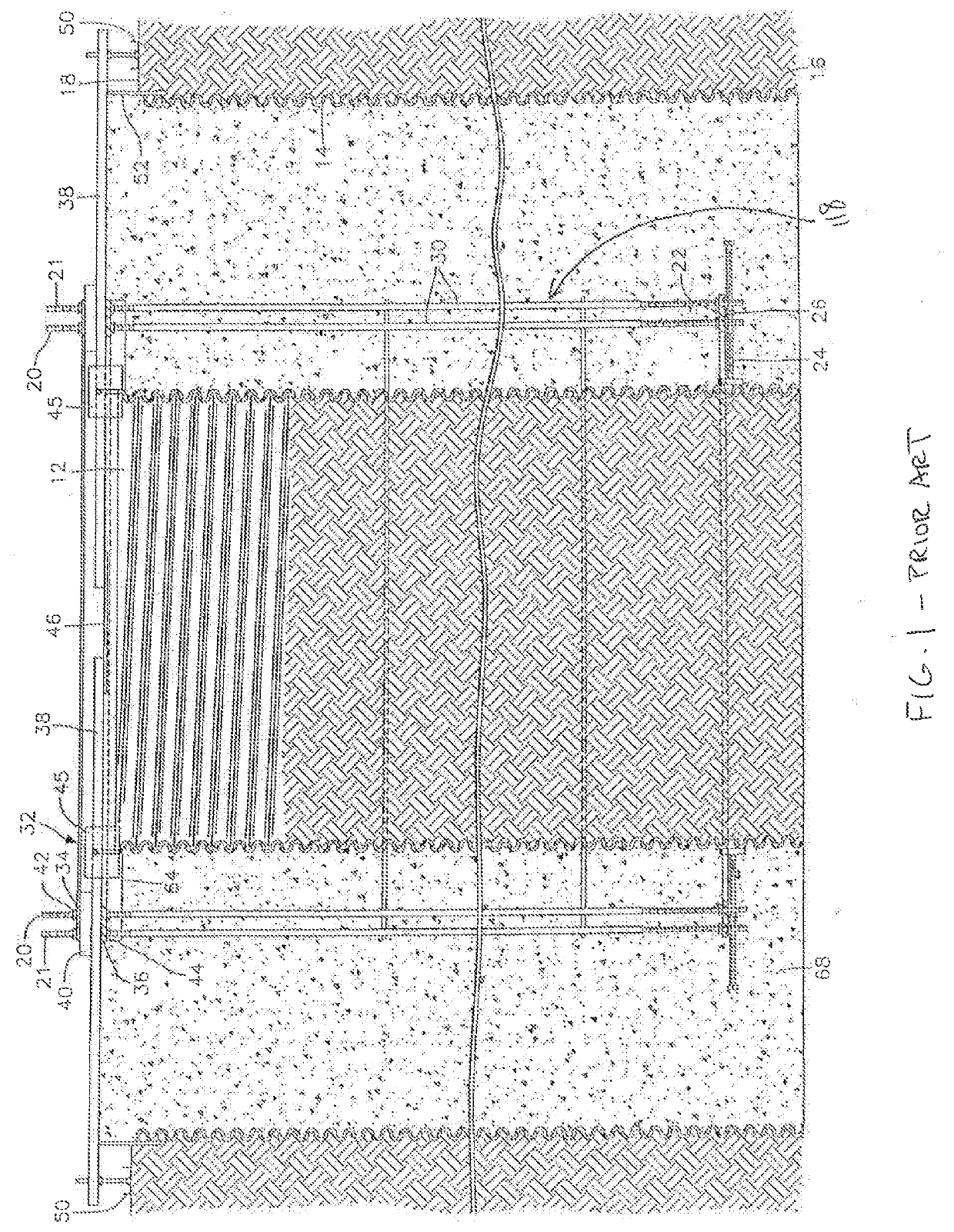
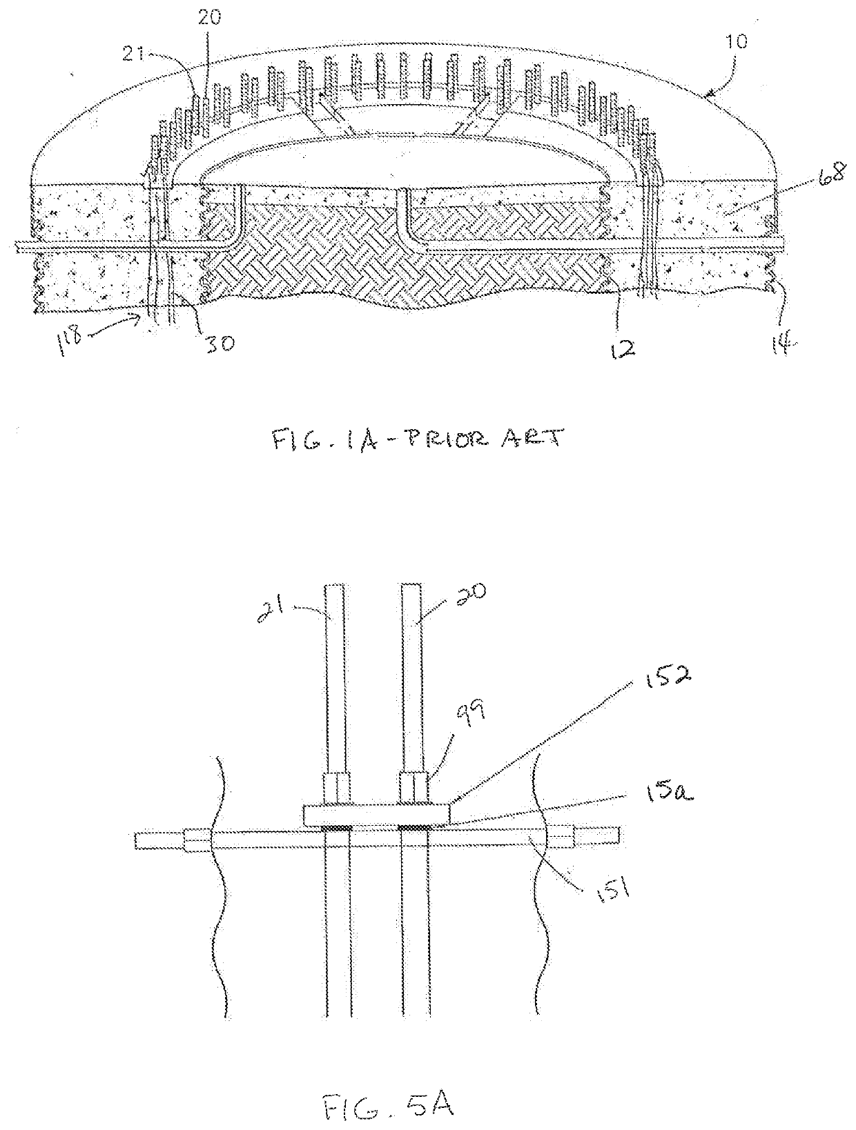
[0050]A tensionless concrete pier foundation like that disclosed in the '417 patent, in which the soil backfill in the center of the foundation is complete below the surface of the ground 18, is shown in FIG. 1. FIG. 1A is a partial view of a similar concrete pier foundation in which the soil backfill is completed to substantially ground level. In both cases, the concrete pier foundation, generally designated by reference numera...
PUM
| Property | Measurement | Unit |
|---|---|---|
| Length | aaaaa | aaaaa |
| Length | aaaaa | aaaaa |
| Diameter | aaaaa | aaaaa |
Abstract
Description
Claims
Application Information