Power plant with heat reservoir

a technology of heat reservoir and power plant, which is applied in the direction of steam engine plants, machines/engines, mechanical equipment, etc., can solve the problems of increasing the cost of natural gas or electrical energy for generators, reducing the efficiency of power generation, and reducing thermal material fatigue. , to achieve the effect of increasing power, promoting the rapid operation readiness of steam circuit, and reducing thermal material fatigu

Active Publication Date: 2019-10-03
SIEMENS ENERGY GLOBAL GMBH & CO KG
View PDF0 Cites 1 Cited by
  • Summary
  • Abstract
  • Description
  • Claims
  • Application Information

AI Technical Summary

Benefits of technology

[0020]Owing to the high storable thermal energy density in the heat reservoir, which is made possible through the use of the phase change material, warmth can be maintained in a particularly advantageous manner from an energy aspect. An electrically operated or fuel-operated auxiliary steam generator is thus no longer necessary. Since the phase change material, after being charged, can provide a substantially consistent temperature level over relatively long periods of time, it is also possible for the steam in the heat reservoir, which thermally interacts with the phase change material, to be kept at a substantially uniform temperature level. This in turn ensures a relatively long supply of thermally conditioned water from the heat reservoir to the thermal functional components of the steam circuit.
[0033]In a further embodiment of the method according to the invention, provision may be made for the discharge of the stored water to be performed when the steam turbine is in a standby state in which the steam turbine is not outputting any power. The discharged water is advantageously thermally treated once again by means of a second heat reservoir and supplied for intermediate superheating. Here, the steam turbine is for example in a standby mode or is possibly even completely removed from the network. By means of the discharge of the water stored in the heat reservoir, it is thus possible for the thermal functional components of the steam circuit to be kept warm, wherein it is for example also possible for a minimum pressure to be provided. This in turn not only promotes the fast operational readiness of the steam circuit but also reduces thermal material fatigue.

Problems solved by technology

The auxiliary steam pressures are however relatively low, as a result of which, in turn, the temperatures for maintaining warmth are upwardly greatly limited.
Furthermore, the heat recovery steam generator generally requires relatively expensive natural gas or electrical energy for providing the required amounts of energy, for which reason this method has economic disadvantages.

Method used


Image

  • Power plant with heat reservoir
  • Power plant with heat reservoir
  • Power plant with heat reservoir

Examples


Embodiment Construction

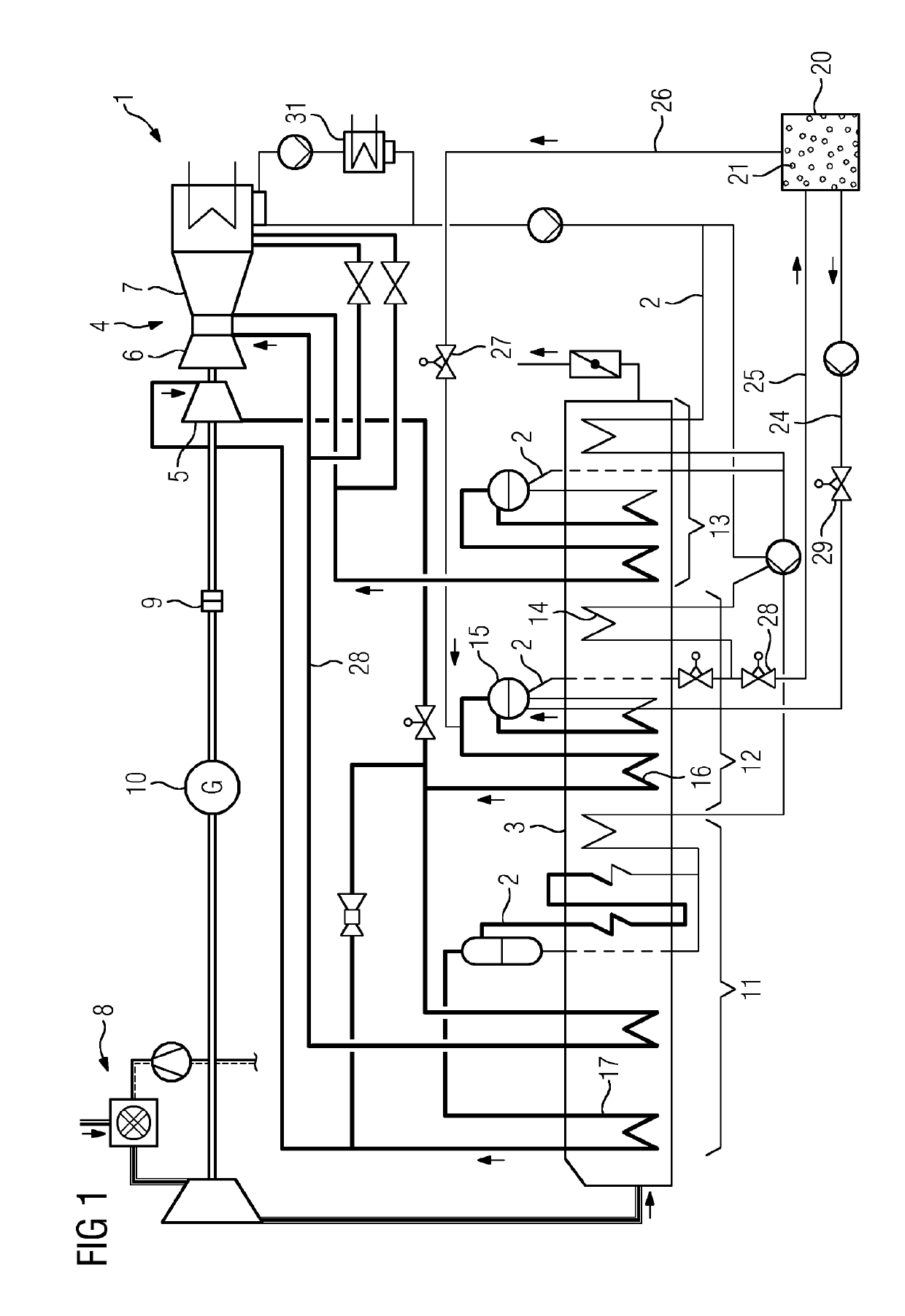
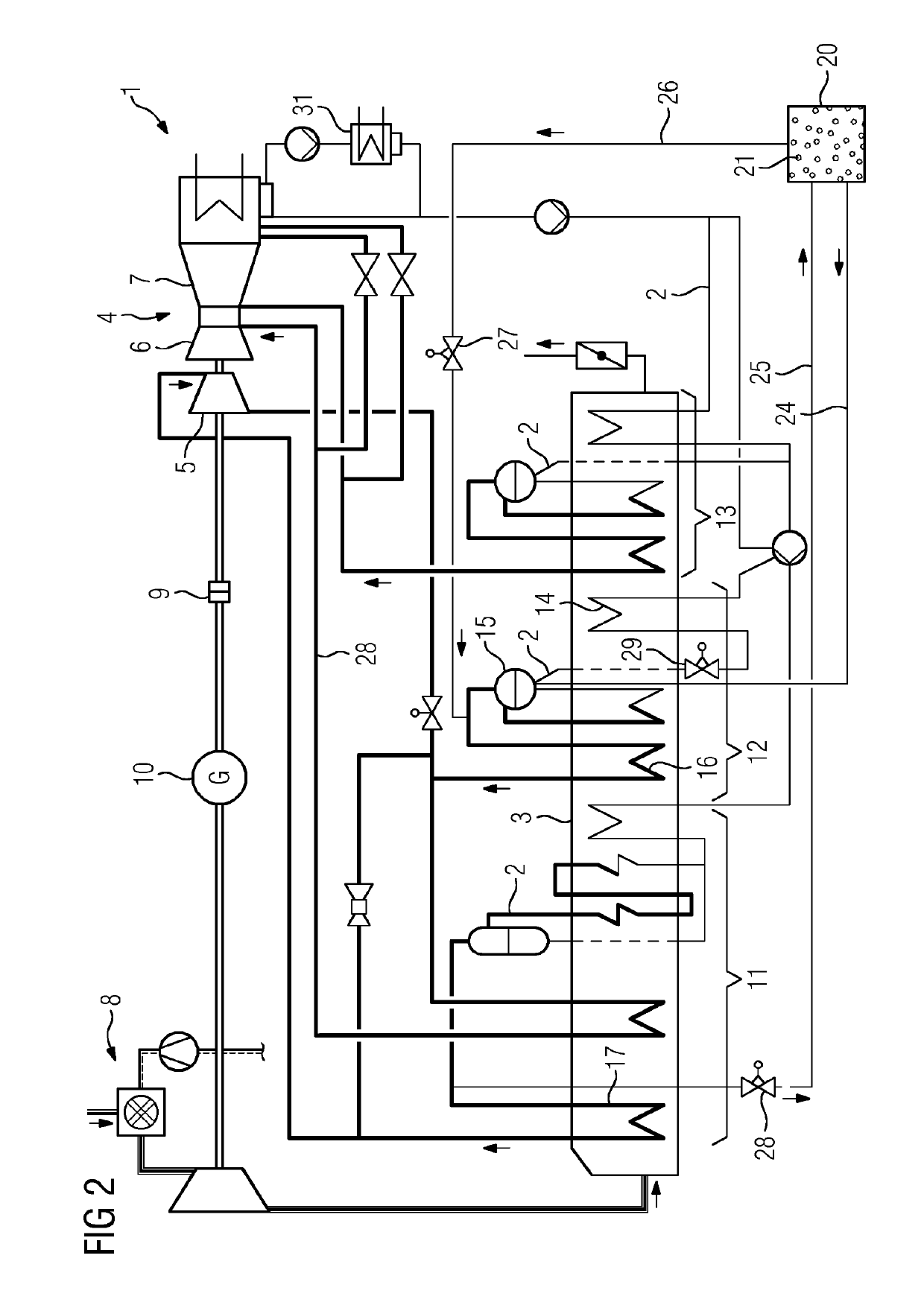
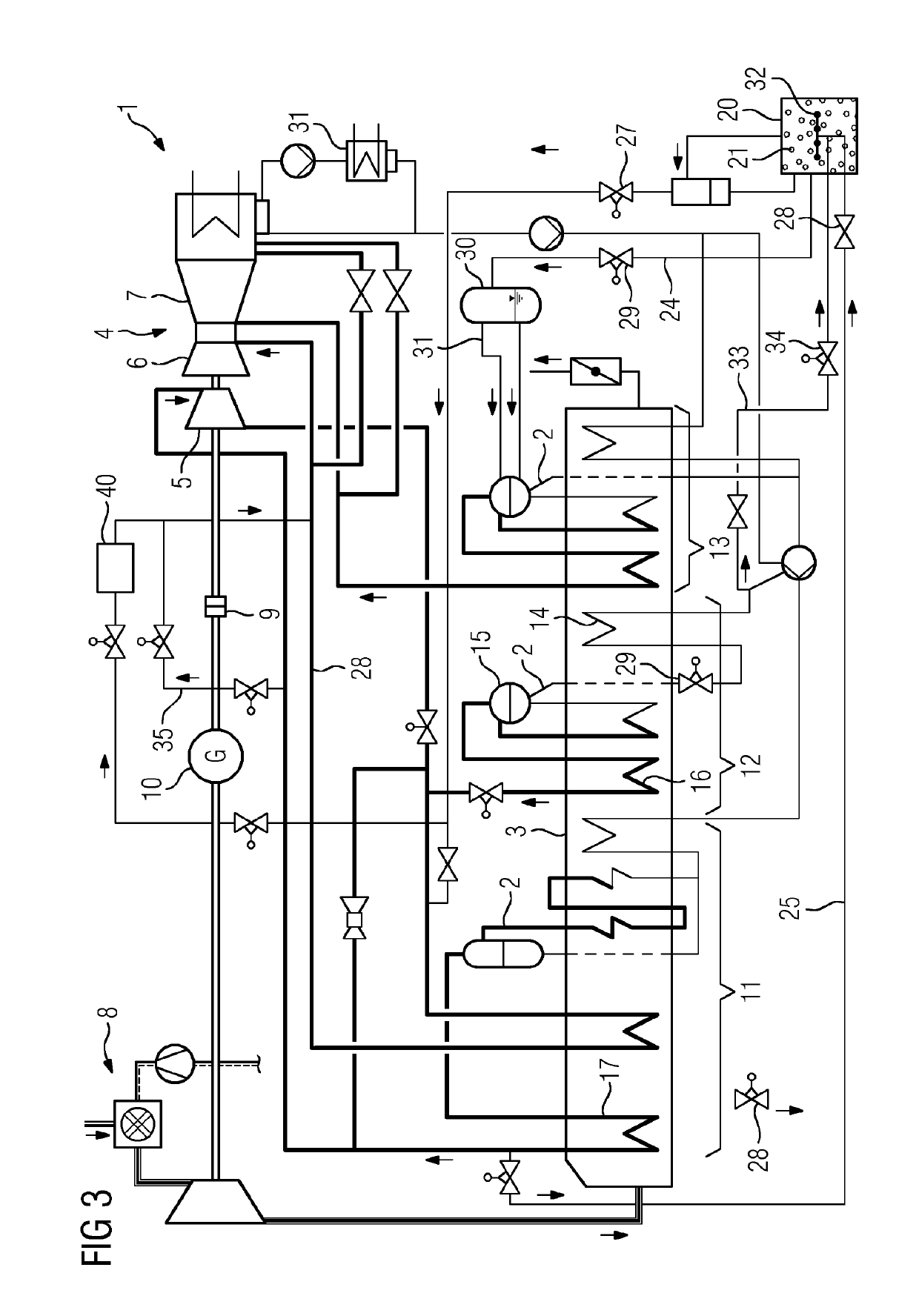
[0043]FIG. 1 shows a schematic diagram view of an embodiment of the power plant 1 according to the invention, in which water in a steam circuit 2 is thermally treated by means of a heat recovery steam generator 3 in order to subsequently convert its thermal energy into rotational mechanical energy by means of a steam turbine 3. The heat recovery steam generator 3 is in particular supplied with thermal energy by means of the exhaust gas of a gas turbine 8, wherein those regions of the steam circuit 2 which are arranged relatively close to the gas turbine in terms of flow are at a relatively high temperature. Within the heat recovery steam generator 3, the individual heat exchangers 3 may be assigned to different regions. The region which has the highest temperatures and pressures is the high-pressure part 11; the part which has the next highest pressures and temperatures is the medium-pressure part 12; and the third part, the low-pressure part 13, has the lowest pressures and tempera...


PUM


Abstract

A power plant having a steam circuit which can be supplied, in the region of a heat recovery steam generator, with thermal energy for producing steam, the steam circuit has, in the region of the heat recovery steam generator, a high pressure part, a medium pressure part and a low pressure part. In addition, a heat reservoir which has a phase change material and which is not situated in the region of the heat recovery steam generator is included, wherein, in order to supply the heat reservoir with thermally processed water, a supply line which leads out from the high pressure part or the medium pressure part is included and a discharge line which leads into the medium pressure part, the low pressure part or a steam turbine is included for discharging thermally processed water from the heat reservoir.

Description

CROSS REFERENCE TO RELATED APPLICATIONS[0001]This application is the US National Stage of International Application No. PCT / EP2017 / 065645 filed Jun. 26, 2017, and claims the benefit thereof. The International Application claims the benefit of German Application No. DE 10 2016 214 447.2 filed Aug. 4, 2016. All of the applications are incorporated by reference herein in their entirety.FIELD OF INVENTION[0002]The present invention relates to a power plant having a steam circuit which can be supplied, in the region of a heat recovery steam generator, with thermal energy for producing steam, and to a method for operating a power plant of said type.BACKGROUND OF INVENTION[0003]The present-day energy market requires power plants which permit flexible operation in order to be able to cover not only relatively fast start-up and run-down times but at the same time also a large power range. In particular because large fluctuations in supplied and demanded quantities of electricity may exist in...

Claims


Application Information

Patent Timeline
Patent Type & Authority Applications(United States)
IPC IPC(8): F01K3/00F01K3/06F01K23/10F01K3/14
CPCF01K3/14F01K3/004F01K23/10F01K3/06F01K23/106F01K13/02F01K13/003
Inventor BECKER, STEFANSCHMID, ERICH
Owner SIEMENS ENERGY GLOBAL GMBH & CO KG
Why Eureka
Try Eureka