Lighting device for vehicles

a technology for lighting devices and vehicles, applied in signalling/lighting devices, vehicle components, lighting and heating apparatus, etc., can solve the problems of large installation space and relatively high cost of mask elements projection, and achieve the effect of reducing the overall height of the lighting devi

Active Publication Date: 2019-10-03
HELLA KG HUECK & CO
View PDF8 Cites 1 Cited by
  • Summary
  • Abstract
  • Description
  • Claims
  • Application Information

AI Technical Summary

Benefits of technology

[0006]It is therefore an object of the present invention to provide a lighting device for vehicles having a micro-optical unit containing a micro-optical array such that a predetermined light distribution can be created in a manner that saves installation space, wherein a reduced overall height of the lighting device is achieved, in particular.

Problems solved by technology

A disadvantage of a conventional lighting device is that it requires a relatively large installation space.
A disadvantage of the known lighting device is that the cost for the projection of the mask elements is relatively expensive.

Method used


Image

  • Lighting device for vehicles
  • Lighting device for vehicles
  • Lighting device for vehicles

Examples


Embodiment Construction

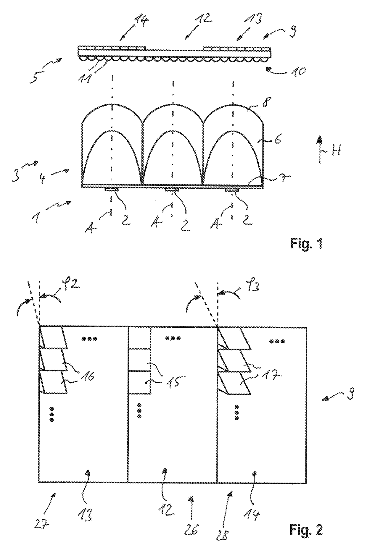
[0020]A lighting device according to the invention for vehicles can be implemented as a headlight that is located, for example, in a front end region of a motor vehicle.

[0021]The lighting device has a light source unit 1 with a multiplicity of light sources 2. The light sources 2 are implemented as LED light sources. They can be applied as light source chips to a printed circuit board that is not shown.

[0022]Located in front of the light source unit 1 in the primary direction of emission H is an optical unit 3, which includes a lighting optical system 4 for parallelizing a light emitted by the light source unit 1 and a projection optical system 5 for projecting the light sources 2 in a near field of the vehicle or onto a measuring screen.

[0023]The lighting optical system 4 has a number of collimators 6 that are arranged next to one another. The collimators 6 each have a preferably flat light incident face 7 and a curved light emergent face 8. The light source 2 in each case is locat...


PUM


Abstract

A lighting device for vehicles having a light source unit containing a number of light sources, having an optical unit that is arranged in front of the light source unit in the primary direction of emission for generating a predetermined light distribution, wherein the optical unit has a micro-optical array with a multiplicity of micro-optical elements arranged in a matrix, wherein a first subarray of the micro-optical array is designed without optics to form a first partial light distribution with a light/dark boundary and with a luminance maximum in a region close to the light/dark boundary, in that at least a second subarray of the micro-optical array has such micro-optical elements. A second partial light distribution is formed below the first partial light distribution in the vertical direction. The light distribution is formed by superimposing the first partial light distribution and the additional partial light distribution.

Description

[0001]This nonprovisional application claims priority under 35 U.S.C. § 119(a) to German Patent Application No. 10 2018 107 214.7, which was filed in Germany on Mar. 27, 2018, and which is herein incorporated by reference.BACKGROUND OF THE INVENTIONField of the Invention[0002]The present invention relates to a lighting device for vehicles having a light source unit containing a plurality of light sources, having an optical unit that is arranged in front of the light source unit in the primary direction of emission for generating a predetermined light distribution, wherein the optical unit has a micro-optical array with a multiplicity of micro-optical elements arranged in a matrix.Description of the Background Art[0003]A lighting device for vehicles is known from DE 10 2005 041 234 A1, which corresponds to US 2008 / 0239746, which is incorporated herein by reference, and includes multiple light source units and multiple optical units. The optical units have different projection charact...

Claims


Application Information

Patent Timeline
Patent Type & Authority Applications(United States)
IPC IPC(8): F21S41/63F21S41/143F21S41/20
CPCF21S41/63F21S41/20F21S41/143F21W2102/10F21S41/26F21S41/275F21S41/285F21S41/151
Inventor FISCHER, BERND
Owner HELLA KG HUECK & CO
Why Eureka
Try Eureka