Fluorescence lifetime measurement apparatus and method capable of finding two or more fluorescence lifetime components by computing least square error through virtual fluorescence distribution model from signal collected in analog mean delay method

a fluorescence lifetime and measurement apparatus technology, applied in the direction of fluorescence/phosphorescence, optical radiation measurement, instruments, etc., can solve the problems of fundamentally limited measurement time of single photon counting method, difficult to independently measure fluorescence lifetime, and inability to find two or more fluorescence lifetime components by computing least square error through virtual fluorescence distribution model. , to achieve the effect of accelerating the calculation of the fluorescence lifetime of samples

Active Publication Date: 2019-10-10
IND ACADEMIC CORP FOUND YONSEI UNIV +1
View PDF7 Cites 2 Cited by
  • Summary
  • Abstract
  • Description
  • Claims
  • Application Information

AI Technical Summary

Benefits of technology

[0010]According to an embodiment of the present invention, even when two or more samples having different fluorescence lifetimes are mixed, it is possible to compute the fluorescence lifetimes of the samples more quickly.
[0011]In detail, even when different types of fluorescence signals are emitted, it is possible to separately measure fluorescence lifetimes.

Problems solved by technology

However, the photodetector with high gain has a fundamental problem of transit time spread (TTS).
However, TCSPC fundamentally has a limitation in measurement time of the single photon counting method.
Furthermore, when a large number of samples having two or more fluorescence lifetimes different from each other are mixed even if a single photon is used, it is more difficult to independently measure the fluorescence lifetimes.

Method used


Image

  • Fluorescence lifetime measurement apparatus and method capable of finding two or more fluorescence lifetime components by computing least square error through virtual fluorescence distribution model from signal collected in analog mean delay method
  • Fluorescence lifetime measurement apparatus and method capable of finding two or more fluorescence lifetime components by computing least square error through virtual fluorescence distribution model from signal collected in analog mean delay method

Examples


Embodiment Construction

Technical Problem

[0007]According to an embodiment of the present invention, there are provided a fluorescence lifetime measurement apparatus and method capable of independently allowing for a high measurement speed even when two or more fluorescence samples having different fluorescence lifetimes are mixed.

Technical Solution

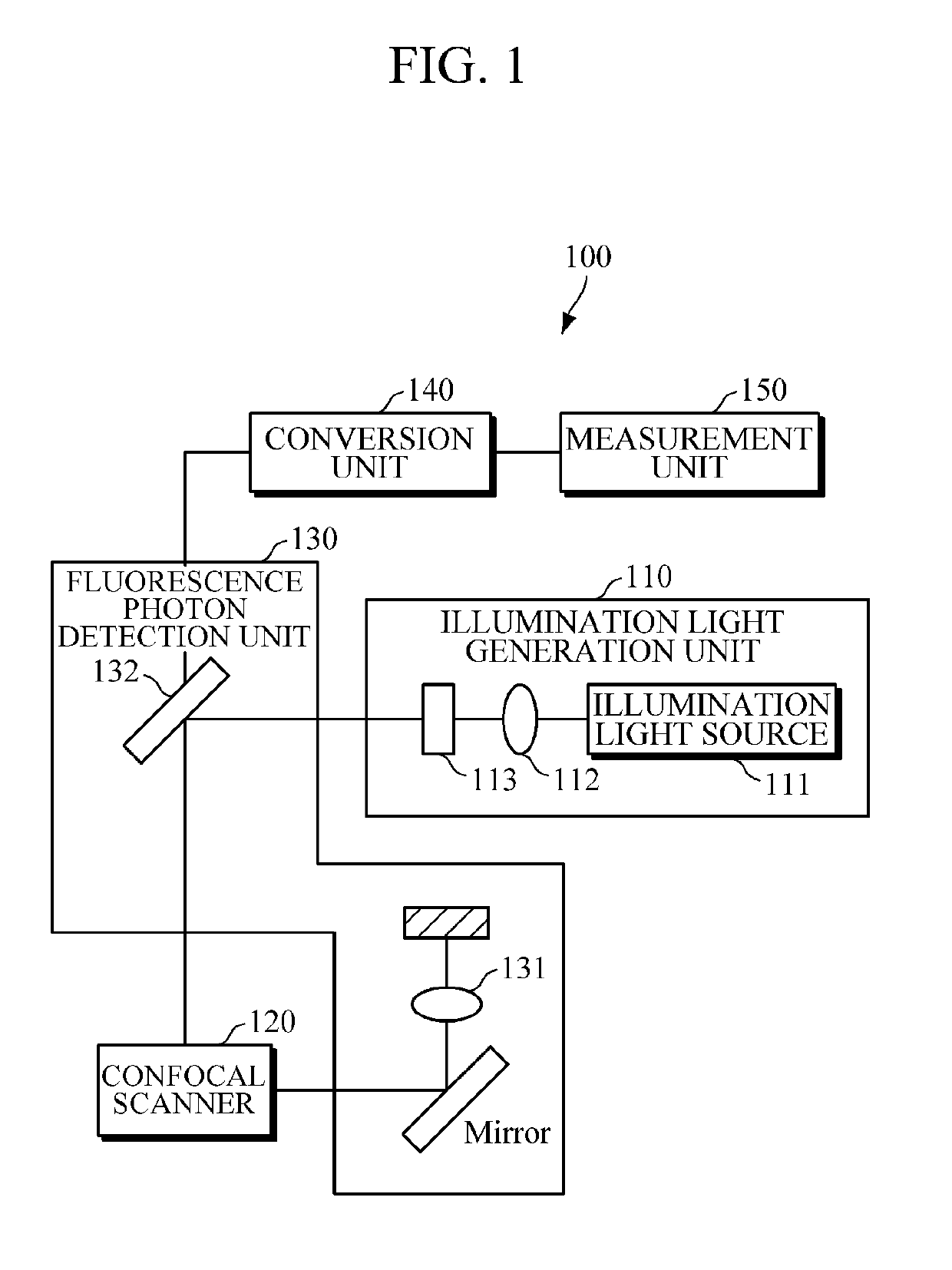
[0008]A fluorescence lifetime measurement apparatus according to an embodiment of the present invention includes an illumination light generation unit configured to generate illumination light, a fluorescence photon detection unit configured to collect a fluorescence signal of fluorescence photons generated by illuminating at least one or more samples including fluorescent molecules with the illumination light, and a measurement unit configured to compute a fluorescence lifetime by applying a least square method to a simulation function and a function of the fluorescence signal.

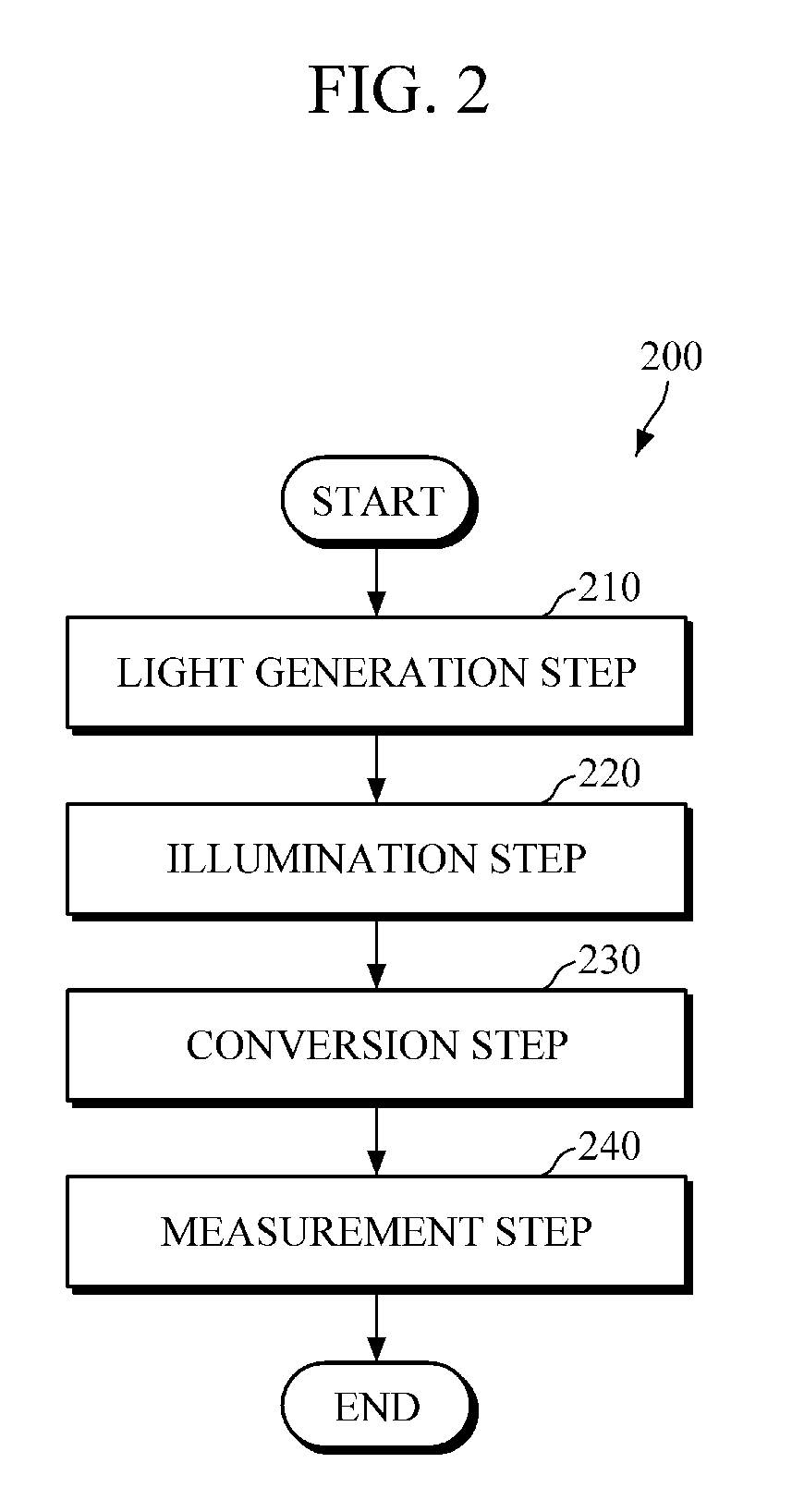
[0009]A fluorescence lifetime measurement method according to an embodiment of the pre...


PUM

PropertyMeasurementUnit
distanceaaaaaaaaaa
fluorescence lifetimeaaaaaaaaaa
wavelengthaaaaaaaaaa

Abstract

A fluorescence lifetime measurement apparatus according to an embodiment of the present invention includes an illumination light generation unit configured to generate illumination light, a fluorescence photon detection unit configured to collect a fluorescence signal of fluorescence photons generated by illuminating at least one or more samples including fluorescent molecules with the illumination light; and a measurement unit configured to compute a fluorescence lifetime by applying a least square method to a simulation function and a function of the fluorescence signal.

Description

TECHNICAL FIELD[0001]The present invention relates to a fluorescence lifetime measurement apparatus and method for measuring a fluorescence lifetime, and more particularly, to a fluorescence lifetime measurement apparatus and method capable of independently measuring two or more mixed samples in the least amount of time.BACKGROUND ART[0002]Microscopes are classified into first-generation optical microscopes, second-generation electron microscopes, and third-generation scanning probe microscopes and are widely used in medical science, molecular biology, new medicine development, and materials engineering.[0003]Recently, however, a fluorescence lifetime microscope has emerged as the core of research. A fluorescence lifetime microscope is an instrument (FLIM-FRET) which is capable of measuring fluorescence resonance energy transfer (FRET) most accurately. FRET is a phenomenon in which energy is transferred from one phosphor to another without the emission or absorption of light when tw...

Claims


Application Information

Patent Timeline
Patent Type & Authority Applications(United States)
IPC IPC(8): G01N21/64G01J1/44
CPCG01N21/6402G01N21/6458G01J2001/4466G01J1/44G01J2001/4453G01J2001/446G01N21/6408G01N21/6486
Inventor KIM, DUG YOUNGHWANG, WON SANGKIM, DONG EUNKANG, MIN GU
Owner IND ACADEMIC CORP FOUND YONSEI UNIV
Why Eureka
Try Eureka