Monitoring camera and condensation suppressing method

a monitoring camera and camera body technology, applied in the field of monitoring cameras and condensation suppressing methods of monitoring cameras, can solve the problems of increased running cost, insufficient condensation suppression, and deterioration of the clarity of the captured image, so as to suppress condensation and icing, suppress the increase in manufacturing cost and running cost, and effectively utilize internal heat generation

Active Publication Date: 2019-10-10
PANASONIC I PRO SENSING SOLUTIONS CO LTD
View PDF0 Cites 10 Cited by
  • Summary
  • Abstract
  • Description
  • Claims
  • Application Information

AI Technical Summary

Benefits of technology

[0005]The present disclosure has been devised in view of the conventional circumstances described above, and it is an object of the present disclosure to provide a monitoring camera and a condensation suppressing method of the monitoring camera, which can suppress an increase in manufacturing cost and running cost and effectively suppress condensation and icing while effectively utilizing internal heat generation.
[0008]According to the present disclosure, it is possible to suppress an increase in manufacturing cost and running cost, and suppress condensation and icing while effectively utilizing internal heat generation.

Problems solved by technology

When the monitoring camera has condensation occurring on a light-transmissive cover provided for protecting a lens, the clarity (that is, visibility) of the captured image deteriorates.
For this reason, there is room for improvement in that air containing water vapor cannot be discharged from the internal space of the closed camera main body, and condensation cannot be suppressed sufficiently.
In addition, suppressing condensation only by driving a heater leads to an increase in running cost.

Method used


Image

  • Monitoring camera and condensation suppressing method
  • Monitoring camera and condensation suppressing method
  • Monitoring camera and condensation suppressing method

Examples


embodiment 1

[0028]First, a monitoring camera 11 according to Embodiment 1 will be described with reference to FIGS. 1 to 7.

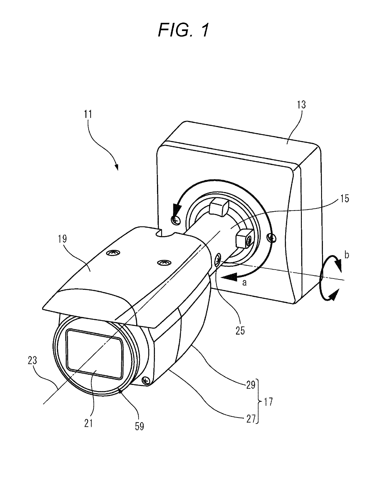
[0029]FIG. 1 is a perspective view showing an example of the monitoring camera 11 according to Embodiment 1. The monitoring camera 11 according to Embodiment 1 is a monitoring camera having a so-called box type (that is, a box-shaped) casing. The environment where the monitoring camera 11 is installed is outdoor, for example. The monitoring camera 11 may be installed indoors such as in a factory, a warehouse, or the like.

[0030]The monitoring camera 11 with a housing 17 is supported on a base portion 13 through an angle portion 15. In Embodiment 1, the housing 17 is a rectangular parallelepiped, for example. It should be noted that the shape of the housing 17 is not limited to this example only. A sunshade 19 is attached to an upper surface side of the housing 17. A light-transmissive cover 21 is attached to a front surface of the housing 17. The angle portion 15 is capable ...

embodiment 2

[0041]Next, a monitoring camera 81 according to Embodiment 2 will be described with reference to FIGS. 8 to 13.

[0042]FIG. 8 is a perspective view showing an example of the monitoring camera 81 according to Embodiment 2. In Embodiment 2, the same reference numerals are given to the equivalent members and equivalent parts as those shown in Embodiment 1, and redundant description is not repeated.

[0043]The monitoring camera 81 according to Embodiment 2 is a monitoring camera having a so-called dome type housing. The environment where the monitoring camera 81 is installed is outdoor, for example. The monitoring camera 81 may be installed indoors such as in a factory, a warehouse, or the like.

[0044]The monitoring camera 81 has a housing 17 and a cover 21.

[0045]In Embodiment 2, the housing 17 is composed of a dome case 83, a main body case 85 (see FIG. 11), and an inner case 87 (see FIG. 11). The dome case 83 is attached to the main body case 85 by a plurality of fixing screws 89. The inne...


PUM


Abstract

A monitoring camera includes a camera unit that has a lens, a housing that has an opening facing a light incident surface of the lens and surrounds the camera unit with a gap which is formed between the housing and the camera unit, a light-transmissive cover that is attached to the opening with spaced apart from the lens to seal off the housing, a fan that is disposed in the gap and circulates an air in the gap, a ventilation hole that is bored in the housing and causes the gap to be open to an outside, a water-proof air-permeable film that covers the ventilation hole, a heater that is provided facing the gap and heats the air, and an infrared light irradiation device that is provided facing the gap and emits infrared light to the outside through the cover and radiates heat into the air.

Description

BACKGROUND OF THE INVENTION1. Field of the Invention[0001]The present disclosure relates to a monitoring camera and a condensation suppressing method of the monitoring camera.2. Background Art[0002]A monitoring camera designed for possible outdoor installations is required to have hermeticity in order to ensure waterproofness, for example. Therefore, moisture (that is, water vapor) contained in the air present in the housing of the monitoring camera is not likely to move to the outside air, and condensation is likely to occur depending on ambient temperature environment. When the monitoring camera has condensation occurring on a light-transmissive cover provided for protecting a lens, the clarity (that is, visibility) of the captured image deteriorates.[0003]JP-A-2017-200109 discloses an image pickup apparatus including an apparatus main body having a lens unit and a heat generating member provided in an internal space thereof, in which the internal space is divided into a first clo...

Claims


Application Information

Patent Timeline
Patent Type & Authority Applications(United States)
IPC IPC(8): H04N5/225G03B17/55G03B17/08
CPCH04N5/2254H04N5/22521G03B17/08G03B17/55H04N5/2256H04N5/2252H04N23/52H04N23/56H04N23/51H04N23/55
Inventor KAWASHIMA, TOMOKIURANO, SEIJIYAMASHITA, MASAHIROYAMAGI, YOICHIRO
Owner PANASONIC I PRO SENSING SOLUTIONS CO LTD
Why Eureka
Try Eureka