

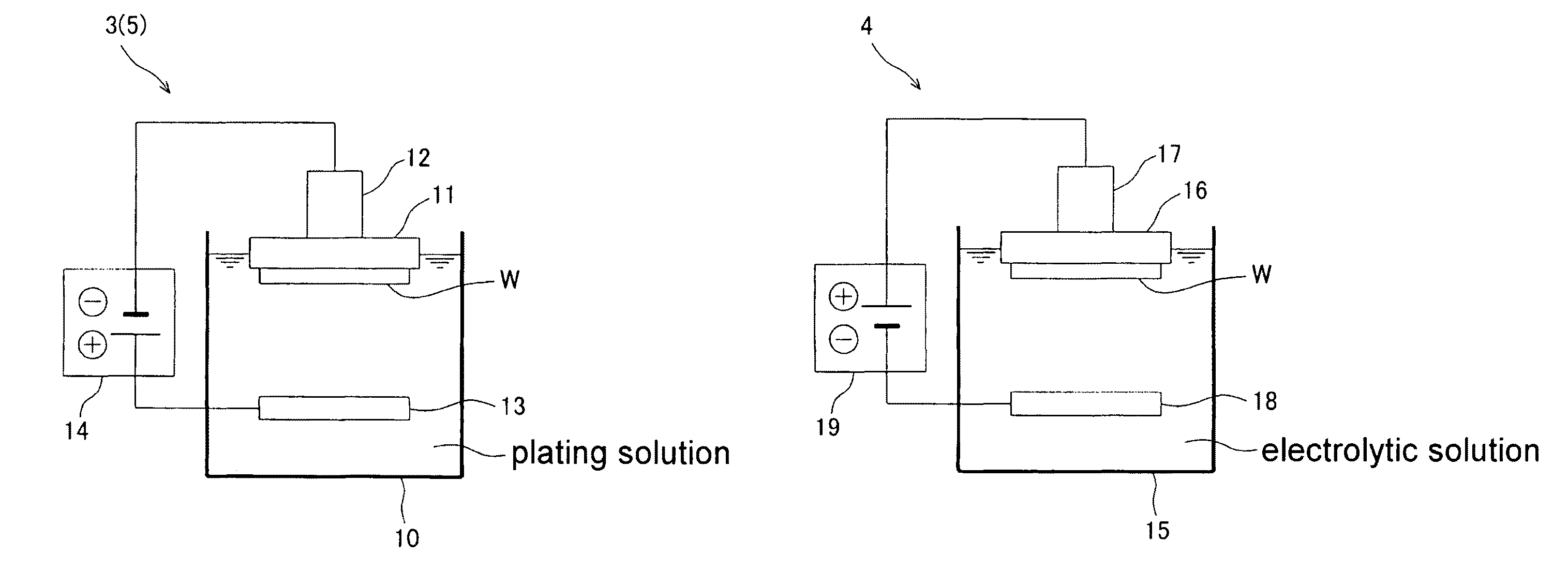
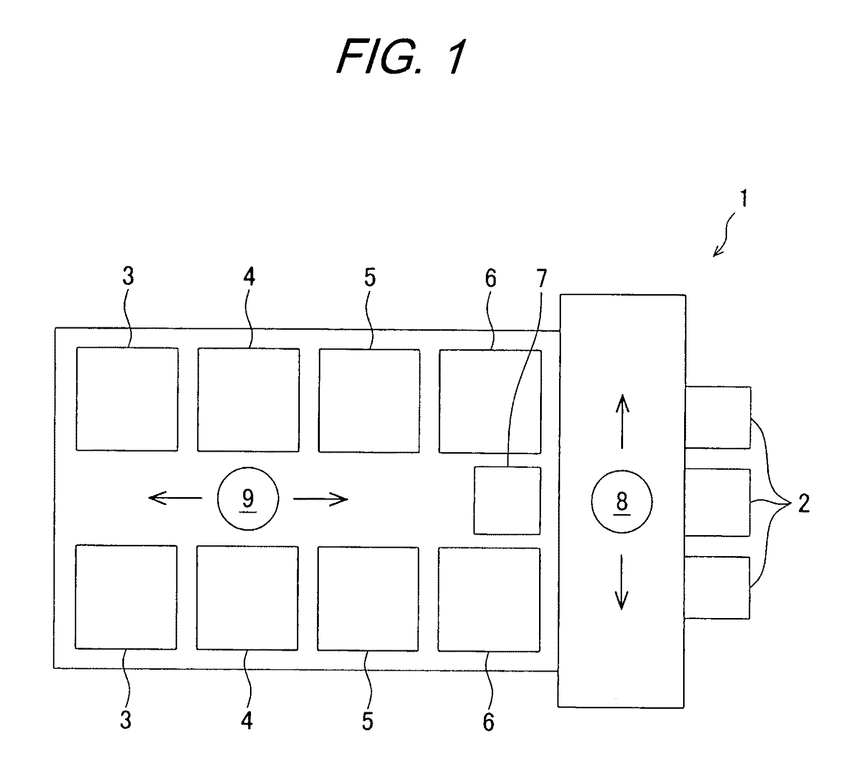
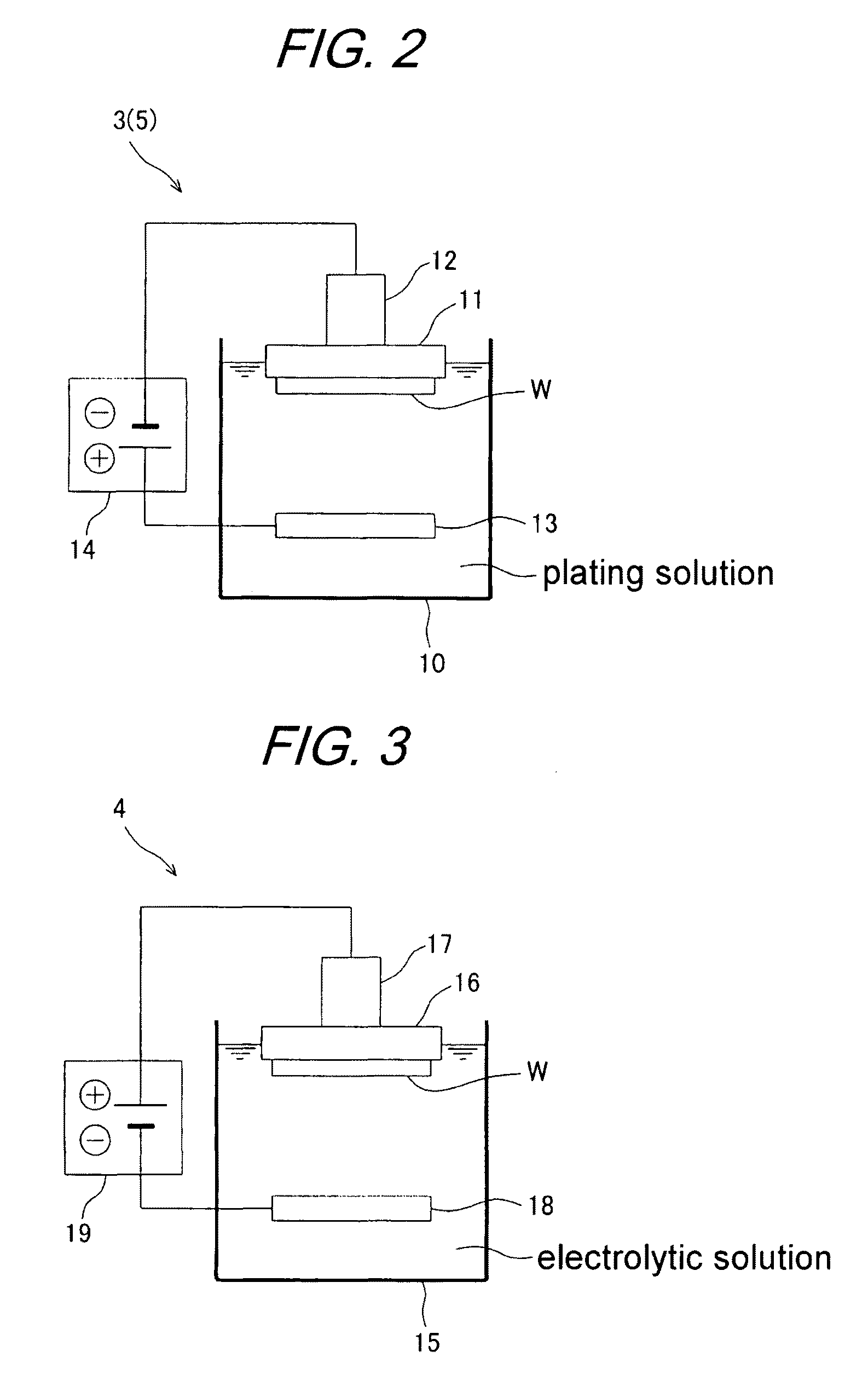
Substrate plating method and apparatus
a technology of substrate and plating method, applied in the direction of superimposed coating process, manufacturing tools, coatings, etc., can solve the problems of weaker inhibition of plating, low plating rate in the bottom of the trench, and accelerate the progress of plating
- Summary
- Abstract
- Description
- Claims
- Application Information
AI Technical Summary
Benefits of technology
Problems solved by technology
Method used
Image

Examples
examples 1 and 2
[0077]Filling of a copper plated film into interconnect trenches provided in a substrate was carried out in the manner described below, using the following baths A to C:
[0078]Bath A: Acidic copper sulfate solution[0079](CuSO4, 0.9 M; H2SO4, 0.56 M)[0080]PEG 0.1 mM[0081]SPS 5.6 μM[0082]Chloride ion (Cl−) 1 mM
[0083]Bath B: Acidic copper sulfate solution[0084](CuSO4, 0.9 M; H2SO4, 0.56 M)[0085]PEG 0.1 mM[0086]SPS None[0087]Chloride ion (Cl−) 50 mM
[0088]Bath C: Acidic copper sulfate solution[0089](CuSO4, 0.9 M; H2SO4, 0.56 M)[0090]PEG 0.1 mM[0091]SPS None[0092]Chloride ion (Cl−) 1 mM
[0093]1. Using the bath A, first plating was carried out at a current density of 100 A / m2 for 10 minutes.
[0094]2. Using the bath B, reverse electrolytic processing was carried out at a current density of 100 A / m2 for 17.5 seconds.
[0095]3. Using the bath C, second plating was carried out at a constant electric potential of −550 mV (vs. mercury sulfate electrode) for one hour (Example 1) or two hours (Example ...
PUM
| Property | Measurement | Unit |
|---|---|---|
| current density | aaaaa | aaaaa |
| concentration | aaaaa | aaaaa |
| current density | aaaaa | aaaaa |
Abstract
Description
Claims
Application Information