Method for electroplating a strip of foam

a foam electroplating and strip technology, applied in the direction of electrolytic coating, surface reaction electrolytic coating, electrolytic coating, etc., can solve the problems of large voltage drop between the cathode and the electroplating bath, the speed of vertical electroplating, and so as to reduce the amount of battery power wasted, improve the resistance of the negative electrode, and improve the effect of electrical conductivity

Inactive Publication Date: 2005-09-13
CIRCUIT FOIL LUXEMBOURG R L
View PDF10 Cites 6 Cited by
  • Summary
  • Abstract
  • Description
  • Claims
  • Application Information

AI Technical Summary

Benefits of technology

[0007]The object of the present invention is to provide an improved method for electroplating a strip of foam, by which a more uniform plating can be achieved. This problem is solved by a method according to the present invention.

Problems solved by technology

Although electroplating in vertical cells is widely used, this technique shows some weaknesses.
Firstly, the speed of electroplating in vertical, planar cells is relatively slow.
Secondly, due to the specific resistance of the foam, a large voltage drop exists between the cathode and the electroplating bath.
This may cause heating of this part of the strip and hence its damaging.
Besides, as the strip is guided by the cathode roll and other idle rolls or driving rolls, the strip somewhat oscillates in the bath, especially as it passes in front of the anode, thereby causing local variations in the metal plating weight.

Method used


Image

  • Method for electroplating a strip of foam
  • Method for electroplating a strip of foam
  • Method for electroplating a strip of foam

Examples


Embodiment Construction

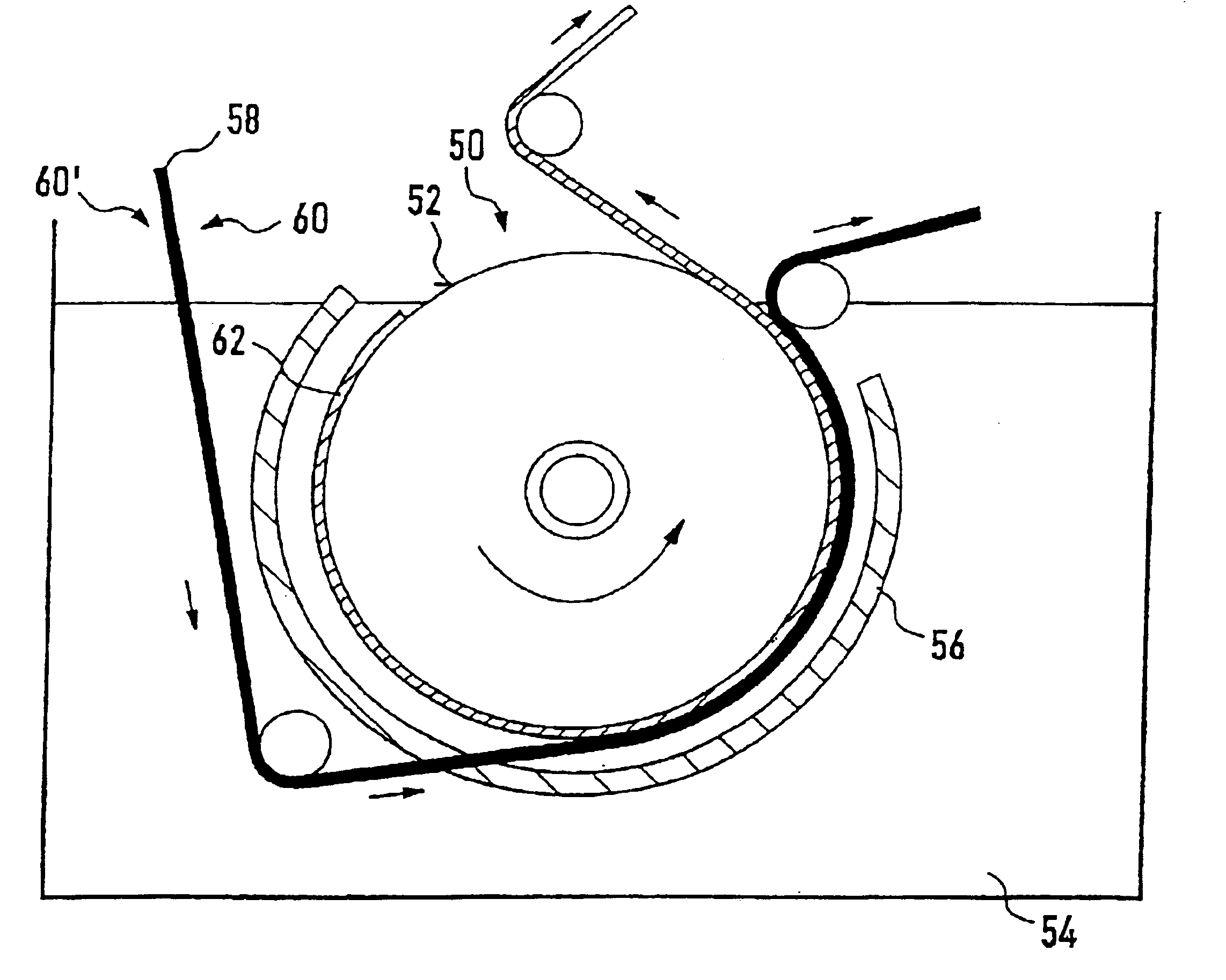
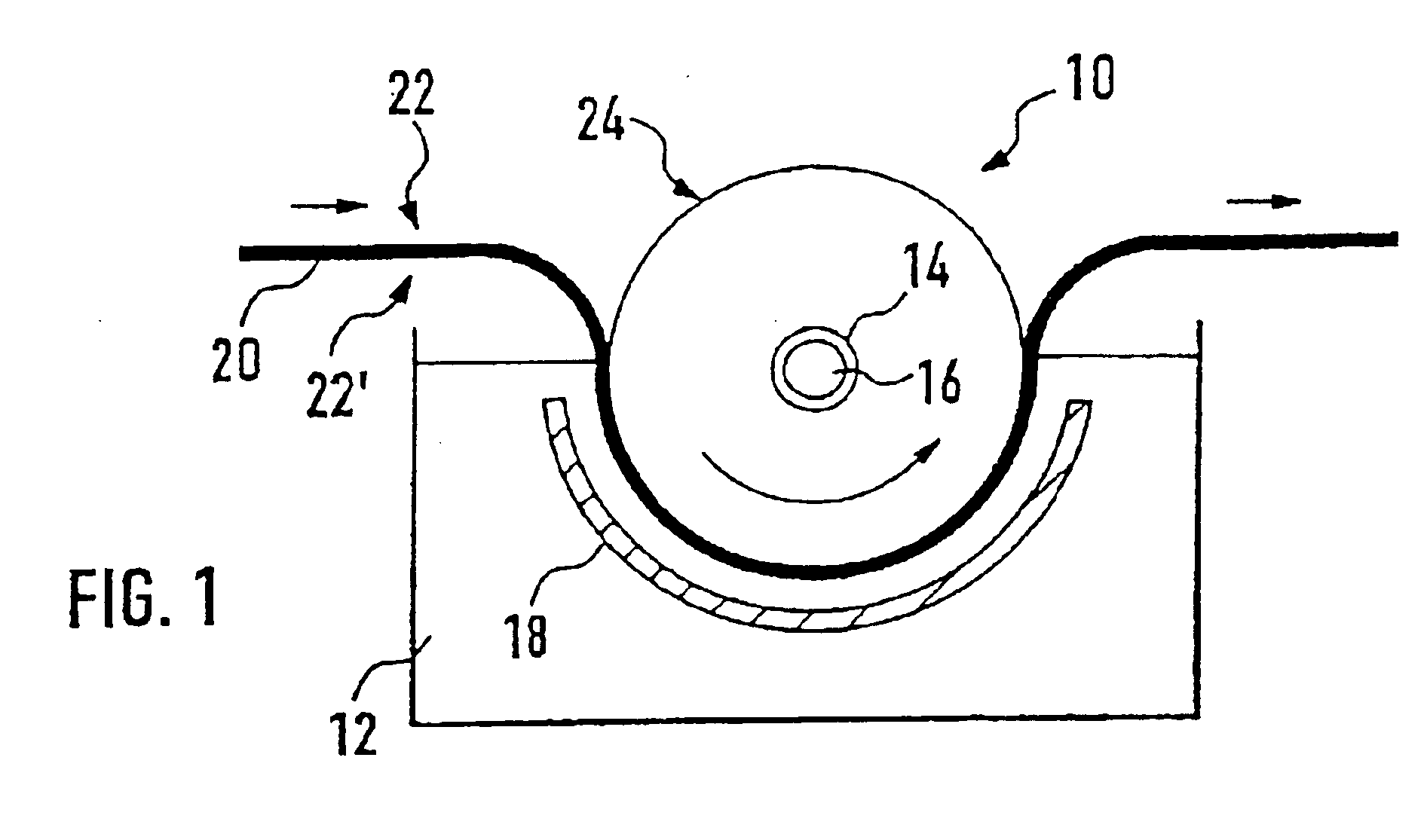
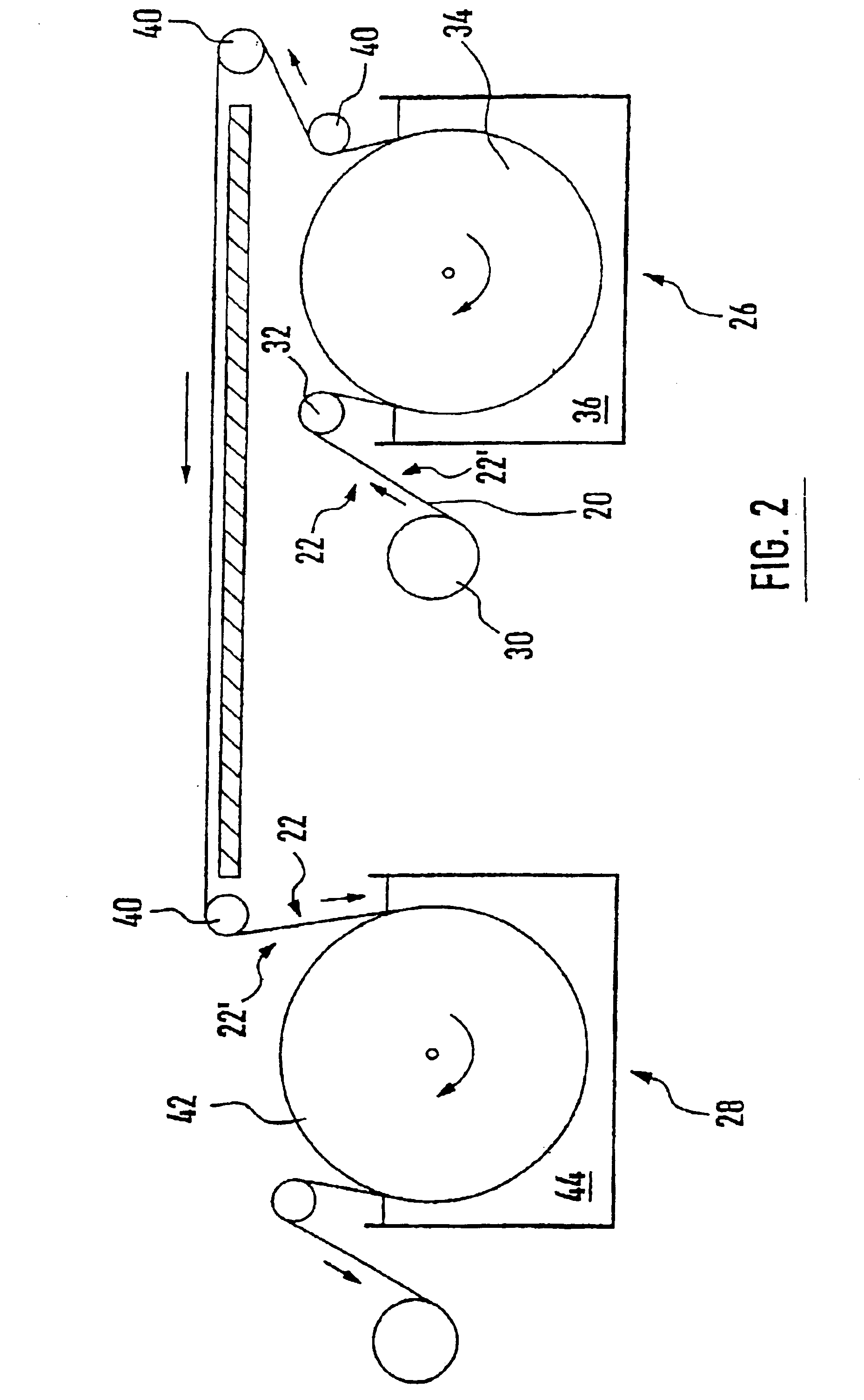
[0031]FIG. 1 illustrates a schematic view of a known method for electroplating a strip of as e.g. described in U.S. Pat. No. 4,326,931. A rotary drum 10, which represents a moving cathode, is immersed in an electroplating bath 12 and rotated by driving means (not shown) at a constant speed. Electric current is supplied through a slip ring 14 mounted on a drum shaft 16 so that a predetermined voltage will be applied between the rotary drum 10 and a cylindrically shaped anode 18 positioned in the vicinity of the drum 10. In a first step of the method, a strip of foam 20 having an electrically conductive surface and two opposite sides 22, 22′ is continuously applied onto the drum 10 so that it travels through the bath 12 in contact with the drum 10. Thus, the strip 20 runs at the same speed as the drum 10 while being electroplated. When the strip 20 has been plated with metal to the desired thickness, it is continuously removed from the cathode drum 10. As can be seen in FIG. 1, the st...


PUM

PropertyMeasurementUnit
thicknessaaaaaaaaaa
electrically conductiveaaaaaaaaaa
thicknessaaaaaaaaaa

Abstract

A method for electroplating a strip of foam having two opposite sides and an electrically conductive surface, including:(a) continuously applying the strip of foam onto a moving cathode immersed in an electroplating bath so that the strip travels through the bath in contact with the moving cathode to electroplate metal on the strip of foam, a first side of the strip of foam facing a working surface of the moving cathode, and(b) continuously removing the electroplated strip of foam from the moving cathode when metal has been plated to a desired thickness;A metal foil is continuously formed by electrodeposition on the working surface of the moving cathode in such a way that the strip of foam is applied at step (a) onto the moving cathode over the metal foil; and, after step (b), the metal foil is continuously removed from the moving cathode.

Description

CROSS-REFERENCE TO RELATED APPLICATIONS[0001]This application is entitled to the benefit of and incorporates by reference in their entireties essential subject matter disclosed in International Application No. PCT / EP01 / 10517 filed on Sep. 12, 2001 and Luxembourg Patent Application No. 90640 filed on Sep. 18, 2000.FIELD OF THE INVENTION[0002]The present invention generally relates to a method for electroplating a strip of foam.BACKGROUND OF THE INVENTION[0003]Conventionally, foam electroplating is carried out in a vertical electroplating cell. Such a cell comprises an electroplating bath and a cathode contact roll positioned outside the electroplating bath. A vertical planar anode is immersed in the bath. A strip of foam having an electrically conductive surface is continuously introduced into the bath and guided so that it travels past the anode prior to reaching the cathode roll. This cathode roll provides a cathode contact, which means that the strip of foam then functions as a ca...

Claims


Application Information

Patent Timeline
Patent Type & Authority Patents(United States)
IPC IPC(8): C25D7/06H01M4/32
CPCC25D7/0614
Inventor KUHN, MARCMASOTTI, LOUISMICHEL, DAMIENYANG, LIYAN
Owner CIRCUIT FOIL LUXEMBOURG R L
Why Eureka
Try Eureka