
Novel electroplating barrel plating device

A new type of barrel plating technology, applied in the electrolytic process, electrolytic components, cells, etc., can solve the problems of limited number of small parts, unsuitable installation and hanging, poor electroplating effect of small parts, etc., to improve work efficiency, save manpower, electroplating uniform effect

Pending Publication Date: 2018-10-23
高益群
View PDF4 Cites 7 Cited by
  • Summary
  • Abstract
  • Description
  • Claims
  • Application Information

AI Technical Summary

Problems solved by technology

[0002] Electroplating is the process of plating a thin layer of other metals or alloys on the surface of certain metals using the principle of electrolysis. It is a process of using electrolysis to attach a layer of metal film to the surface of metal or other material parts to prevent metal oxidation. Rust, improve wear resistance, electrical conductivity, reflective, anti-corrosion copper sulfate, etc. and enhance the appearance. The outer layer of many coins is also electroplated. Electroplating requires electroplating equipment, but many small coins that require electroplating treatment Due to the influence of shape, size and other factors, the parts cannot or are not suitable for hanging, so it is impossible to use the method of rack plating for electroplating treatment. Moreover, the number of small parts in the basket used for basket plating is limited. The plating effect of small parts is not good

Method used


Image

  • Novel electroplating barrel plating device
  • Novel electroplating barrel plating device

Examples


Embodiment Construction

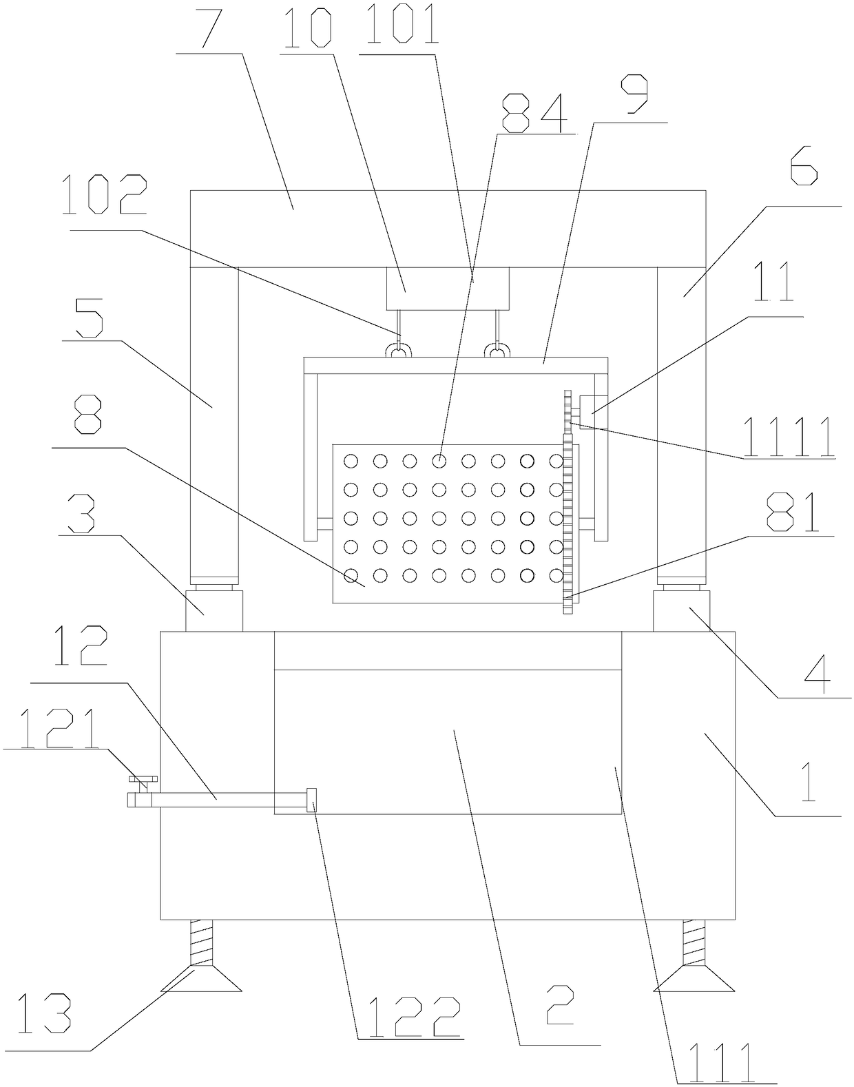
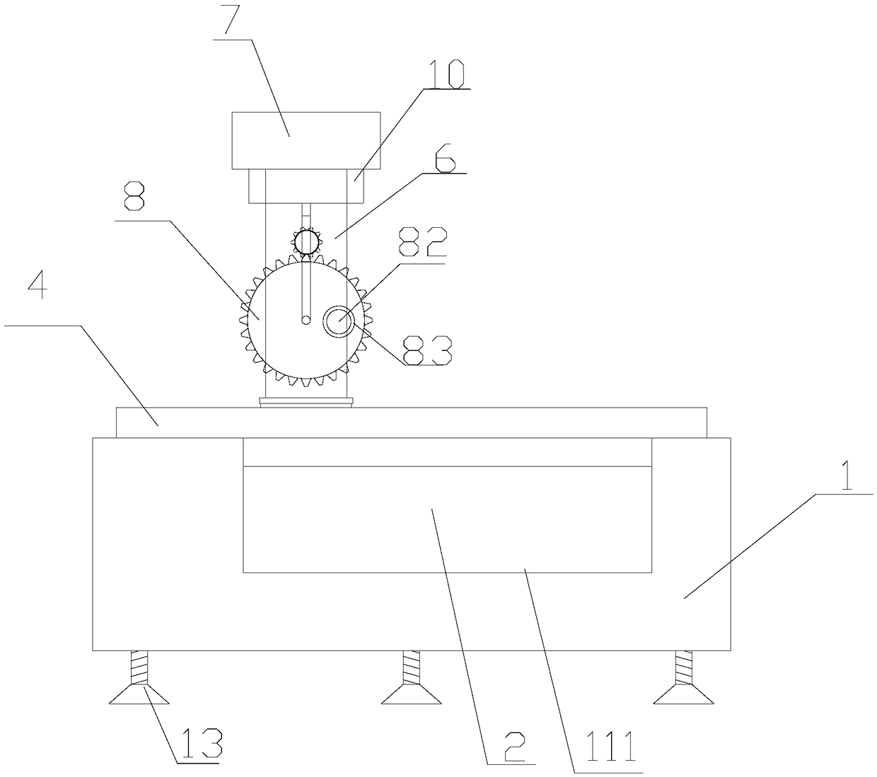
[0015] refer to figure 1 and figure 2 , a novel electroplating barrel plating device of the present invention, comprising a main frame base 1, an electroplating solution 2, a first electric cylinder 3, a second electric cylinder 4, a first pillar 5, a second pillar 6, a horizontal plate 7, a barrel plating Barrel 8, barrel plating barrel fixing bracket 9, lifting device 10, motor 11, the upper end of the main frame base 1 is provided with an electroplating pool cavity 111, and the electroplating pool cavity 111 is provided with an electroplating solution 2, and the described electroplating pool cavity 111 is provided with an electroplating solution 2. The two sides of the electroplating cell cavity 111 at the upper end of the main frame base 1 are respectively provided with a first electric cylinder 3 and a second electric cylinder 4, the first electric cylinder 3 and the second electric cylinder 4 are arranged relatively in parallel, and the first electric cylinder 4 The up...


PUM


Abstract

The invention discloses a novel electroplating barrel plating device comprising a main frame base, an electroplating liquid, a first electric cylinder, a second electric cylinder, a first pillar, a second pillar, a cross plate, a barrel plating bucket, a barrel plating bucket fixing bracket, a lifting device and a motor. The upper end of the main frame base is provided with an electroplating battery chamber, and the electroplating battery chamber is internally provided with the electroplating liquid; two sides, at the upper end of the main frame base, of the electroplating battery chamber areprovided with the first electric cylinder and the second electric cylinder respectively; the first electric cylinder and the second electric cylinder are relatively parallel to each other; the upper end of a sliding part of the first electric cylinder is provided with the first pillar. A workpiece is placed in the barrel plating bucket, hoisted into the electroplating battery chamber and processed; the workpiece is turned over by rotation of a roll barrel, the surface of the workpiece is electroplated more uniformly, all dead corners of the workpiece can be electroplated, and the electroplating effect cannot be affected by backlogging; the workpiece in the barrel plating bucket and the roll barrel is convenient to transport through the cooperation of the electric cylinders and the liftingdevice, the manpower is saved and the work efficiency is improved.

Description

【Technical field】 [0001] The invention relates to the technical field of electroplating, in particular to the technical field of electroplating barrel plating. 【Background technique】 [0002] Electroplating is the process of plating a thin layer of other metals or alloys on the surface of certain metals using the principle of electrolysis. It is a process of using electrolysis to attach a layer of metal film to the surface of metal or other material parts to prevent metal oxidation. Rust, improve wear resistance, electrical conductivity, reflective, anti-corrosion copper sulfate, etc. and enhance the appearance. The outer layer of many coins is also electroplated. Electroplating requires electroplating equipment, but many small coins that require electroplating treatment Due to the influence of shape, size and other factors, the parts cannot or are not suitable for hanging, so it is impossible to use the method of rack plating for electroplating treatment. Moreover, the numb...

Claims


Application Information

Patent Timeline
Patent Type & Authority Applications(China)
IPC IPC(8): C25D17/20C25D17/00C25D21/06
CPCC25D17/00C25D17/20C25D21/06
Inventor 高益群
Owner 高益群
Learn More