Image forming apparatus

Active Publication Date: 2019-10-17
CANON KK
View PDF0 Cites 3 Cited by
  • Summary
  • Abstract
  • Description
  • Claims
  • Application Information

AI Technical Summary

Benefits of technology

[0015]According to the present invention, individual detected temperatures from a plurality of temperatur

Problems solved by technology

However, when a thermistor is formed in each heat generating area, as in PTL 1, the number of wires connected to the ther

Method used


Image

  • Image forming apparatus
  • Image forming apparatus
  • Image forming apparatus

Examples


first embodiment

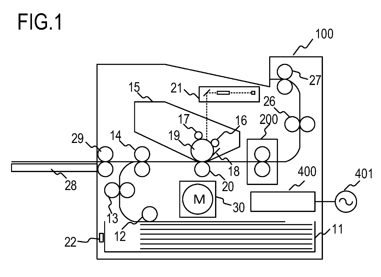
[0026]FIG. 1 is a schematic sectional view of an electrophotographic-system image forming apparatus (a laser printer 100) according to an embodiment of the present invention. A copier, a printer, or the like using an electrophotographic system or an electrostatic recording system may be cited as image forming apparatuses to which the present invention can be applied, but here, a case in which the present invention is applied to a laser printer will be described. Further, a fixing unit that fixes an unfixed toner image (a developer image) onto a recording material after the toner image has been transferred onto the recording material, a gloss applying apparatus that improves the gloss value of the toner image by reheating the toner image after the toner image has been fixed onto the recording material, and so on may be cited as image heating apparatuses installed in the image forming apparatus.

[0027]When a print signal is generated, a laser beam modulated in accordance with image inf...

second embodiment

[0055]Next, a second embodiment relating to a heater 600 in which, in contrast to the heater 300 described in the first embodiment, the heat generating areas are divided in the longitudinal direction will be described, the second embodiment serving as a modified example of the heating element pattern. Identical reference symbols have been used for similar configurations to the first embodiment, and description thereof has been omitted.

[0056]FIGS. 6A and 6B show a sectional view and a planar view of the heater 600. The sectional view in FIG. 6(A) is similar to the first embodiment. On the back surface layer 1 of the heater 600, a conductor 601 and a conductor 603 are provided on the substrate 305. The conductor 601 is divided into a conductor 601a disposed on the upstream side of the transport direction of the recording material P, and a conductor 601b disposed on the downstream side. The conductor 603 is divided into conductors 603-1 to 603-7 in the longitudinal direction of the sub...


PUM


Abstract

In a heater including a plurality of first temperature detection elements that are arranged at predetermined intervals in a longitudinal direction of a substrate and respectively output temperature signals individually, and a plurality of second temperature detection elements that are arranged at predetermined intervals in positions that differ from the positions of the first temperature detection elements in a lateral direction that is orthogonal to the longitudinal direction but correspond to the positions of at least some of the plurality of first temperature detection elements in the longitudinal direction, and that output a single temperature signal obtained by adding individual temperature signals together, the individual temperature signals included in the single temperature signal are acquired on the basis of the plurality of temperature signals output by the plurality of first temperature detection elements and the single temperature signal.

Description

CROSS-REFERENCE TO RELATED APPLICATIONS[0001]This application is a Continuation of International Patent Application No. PCT / JP2017 / 046105, filed Dec. 22, 2017, which claims the benefit of Japanese Patent Application No. 2016-251541, filed Dec. 26, 2016, which is hereby incorporated by reference herein in its entirety.BACKGROUND OF THE INVENTIONField of the Invention[0002]The present invention relates to an image forming apparatus including an image heating apparatus.Background Art[0003]A conventional image heating apparatus, such as a fixing apparatus provided in an image forming apparatus that uses an electrophotographic system, an electrostatic recording system, or the like, is configured to include a tubular film, a flat plate-shaped heater that is in contact with an inner surface of the film, and a roller that forms a nip portion together with the heater via the film. The flat plate-shaped heater may be divided into heat generating areas in a longitudinal direction of the heater...

Claims


Application Information

Patent Timeline
IPC IPC(8): G03G15/20G03G15/00
CPCG03G15/205G03G15/5062H05B3/00G03G15/2042G03G2215/2035G03G15/2053
Inventor OGURA, RYOTASHIMURA, YASUHIRO
Owner CANON KK
Why Eureka
Try Eureka