
Locomotive control system

a technology for locomotives and control systems, applied in the direction of railway signalling, railway signalling, signalling indicators on vehicles, etc., can solve the problems of unnecessari complexity of the control system of some vehicles, unfavorable communication between components, and many different communication networks within the vehicl

Inactive Publication Date: 2019-10-24
GE GLOBAL SOURCING LLC
View PDF0 Cites 20 Cited by
  • Summary
  • Abstract
  • Description
  • Claims
  • Application Information

AI Technical Summary

Benefits of technology

The patent describes a method for ensuring timely communication between devices in a control system while also allowing non-critical communications to pass through without interrupting the timing of the critical communications. The method involves determining available bandwidth for both types of communications, and then using that bandwidth to transfer the non-critical communications without interfering with the critical ones. The method also allows for quick adjustments in bandwidth to handle changes in communication needs without shutting down the control system. Overall, the method ensures that the control system operates efficiently and without causing any delays in communications.

Problems solved by technology

The control systems of some vehicles may be complex in that many components communicate with each other.
Not all of these components, however, may communicate signals of the same or similar importance or criticality to operation of the vehicle.
But, using many different communication networks within a vehicle can present unnecessarily complexity.
For example, some components may not be able to communicate with each other without the communications being relayed and / or converted by another component.
As the number of networks and components needed to communicate within a vehicle control system increases, the potential points of failure and complexity of ensuring that communications successful occur increase.
Failure to deliver some data at or within designated times may result in failure of the powered system, which can have significant consequences.
For example, the failure to deliver sensor data to a control system of a locomotive or rail vehicle system can result in the locomotive or rail vehicle system not applying brakes early enough to avoid a collision.
Other control systems may fail to implement protective measures to avoid damage or injury to the systems or other equipment if data is not supplied at or within the designated times. Without timely information, feedback control systems cannot maintain performance and stability.
Constructing and maintaining separate communication networks is redundant and expensive.
Both solutions add increased cost and complexity to the control system or powered system.
Dedicating wires or networks to communication of data between certain devices may require duplication of communication and network hardware, which can significantly add to the cost and time in establishing, maintaining, and repairing the networks.
But, the DDS is not integrated with the network, and the network may need to be manually configured to create the network connections for the devices communicating within the DDS.
Some offline tools can automate the configuration changes to a network to allow for changes in communication between the devices, but this can require a system shutdown and restart, which can be unsafe and / or costly with some control systems.
With the top-down trend, however, a networking section of an application is completely re-written, which may be undesirable, and the re-writing puts the burden of writing to the correct path on the application developer.
With the bottom-up trend, the solution space may be limited to switches with deep packet inspection only.

Method used


Image

  • Locomotive control system
  • Locomotive control system
  • Locomotive control system

Examples


Embodiment Construction

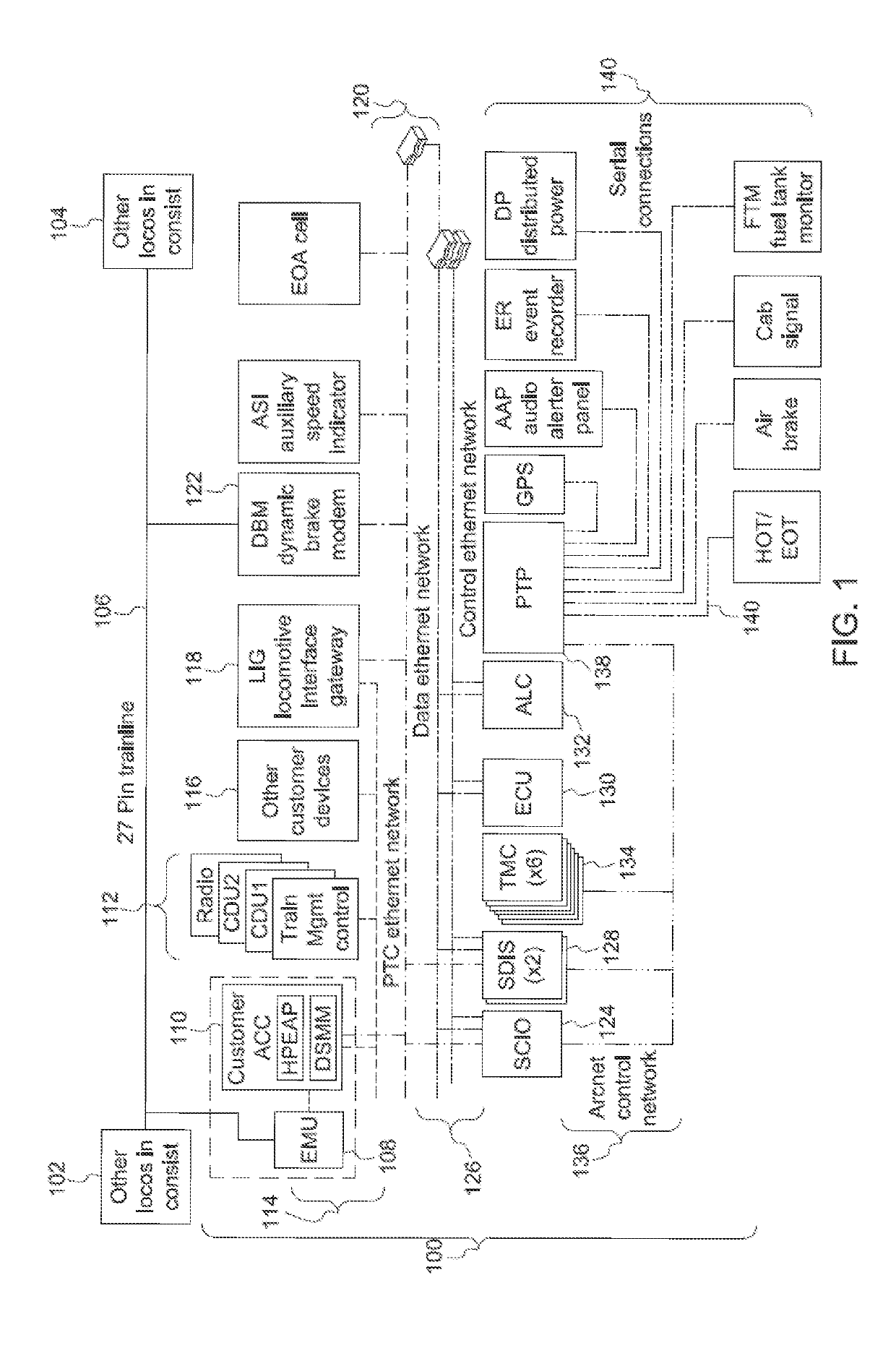
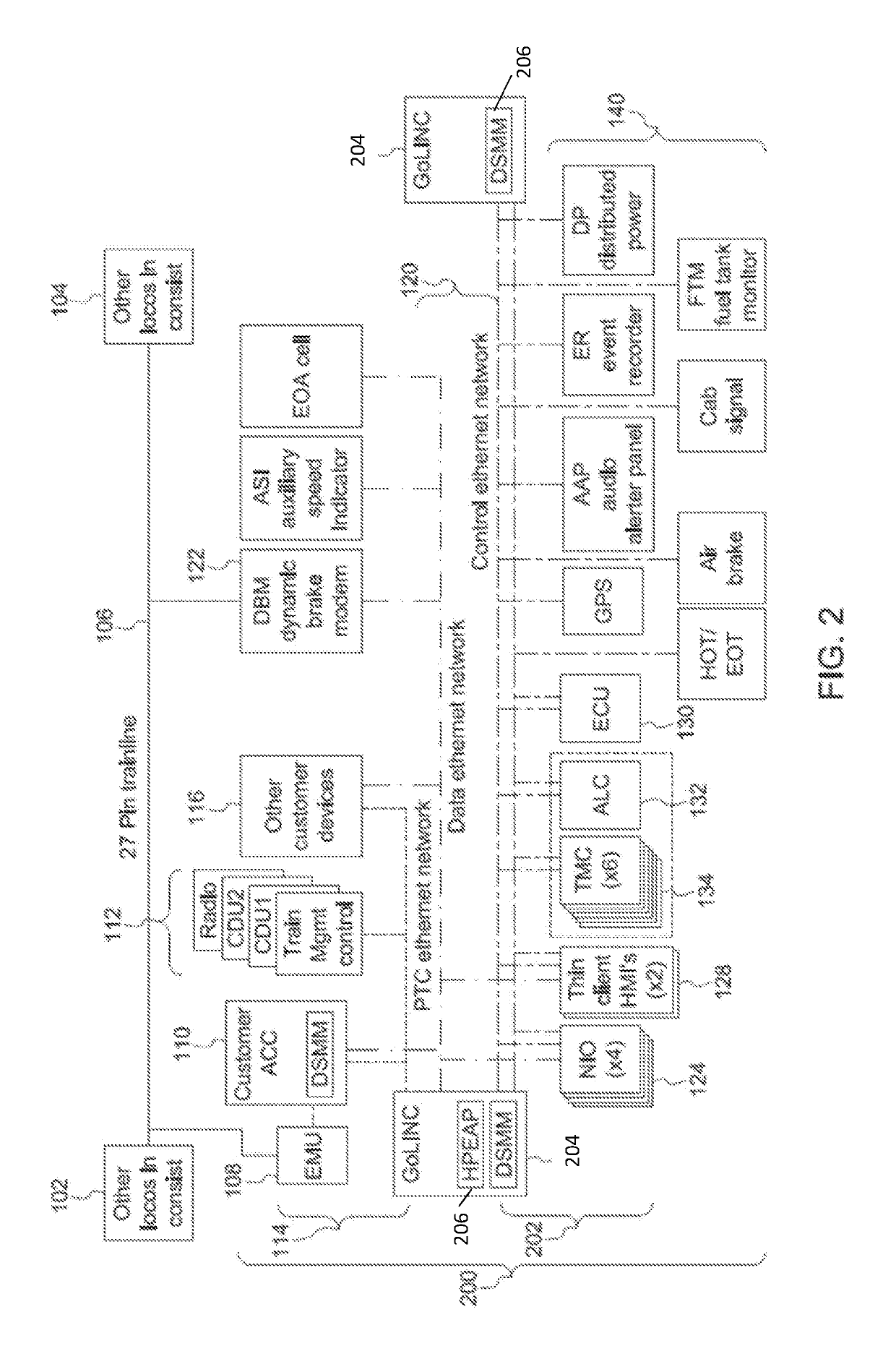
[0052]FIG. 1 illustrates one example of a vehicle control system 100. The vehicle control system 100 may be disposed onboard one or more vehicles of a vehicle system. For example, the control system 100 may be disposed onboard a locomotive of a rail vehicle system formed from the locomotive and one or more other locomotives 102, 104. The locomotives in the vehicle system are communicatively coupled by a wired connection 106, such as a 27-pin trainline cable. Other control systems identical or similar to the control system 100 shown in FIG. 1 may be disposed onboard the other locomotives 102, 104, with the various control systems 100 communicatively coupled (e.g., able to communicate with each other) via the wired connection 106. While the control system 100 is shown as being disposed onboard a locomotive of a rail vehicle system, alternatively, the control system 100 may be disposed onboard another type of vehicle. For example, the control system 100 may be disposed onboard an autom...


PUM


Abstract

A locomotive control system includes one or more processors configured to determine quality of service (QoS) parameters of locomotive devices communicating data with each other in an Ethernet network that is configured as a time sensitive network (TSN) and that is onboard a locomotive. The one or more processors also are configured to determine available communication pathways in the TSN through which the locomotive devices are able to communicate the data. The one or more processors also are configured to select one or more of the available communication pathways and to designate communication times at which the data is communicated between the locomotive devices to satisfy the QoS parameters of the locomotive devices.

Description

FIELD[0001]Embodiments of the present disclosure generally relate to systems and methods for controlling and communicating with rail vehicles.BACKGROUND[0002]Movement of vehicles is controlled by control systems that receive user input and communicate control signals to components of the vehicles to implement actions dictated by the user input. For example, a vehicle operator may depress a pedal, move a lever, or take other action to change a throttle setting of a vehicle or activate a brake of the vehicle. Responsive to this operator input, a control system of the vehicle may communicate signals (e.g., changes in voltages, currents, etc.) to engines, motors, brakes, etc., of the vehicle to implement the operator input (and change the throttle or activate the brake, as appropriate).[0003]The control systems of some vehicles may be complex in that many components communicate with each other. Not all of these components, however, may communicate signals of the same or similar importan...

Claims


Application Information

Patent Timeline
Patent Type & Authority Applications(United States)
IPC IPC(8): B61L15/00B61L23/00H04L29/08
CPCH04L67/12H04L67/322B61L23/005H04L12/56H04L47/11H04L65/80B61L15/0072H04L45/50B61L15/0036H04L65/1069H04L47/225H04L47/2416H04L47/2441H04L47/24H04L47/28H04L67/61
Inventor MONG, TAB ROBERTBUSH, STEPHEN FRANCIS
Owner GE GLOBAL SOURCING LLC
Learn More