Traffic control system, traffic information output device, traffic control method, and recording medium

a traffic control system and traffic information technology, applied in traffic control systems, instruments, marketing, etc., can solve problems such as unnecessary congestion, traffic congestion becoming particularly serious, and traffic dispersion by detours not being performed as expected

Active Publication Date: 2019-10-24
NEC CORP
View PDF4 Cites 4 Cited by
  • Summary
  • Abstract
  • Description
  • Claims
  • Application Information

AI Technical Summary

Benefits of technology

[0016]An advantageous effect of the present invention is that service quality provided by a toll-way can be maintained.

Problems solved by technology

Traffic congestion is becoming particularly serious in urban areas where population growth is advancing.
Thus, traffic dispersion by detours is not performed as expected, and unnecessary congestion is occurring.

Method used


Image

  • Traffic control system, traffic information output device, traffic control method, and recording medium
  • Traffic control system, traffic information output device, traffic control method, and recording medium
  • Traffic control system, traffic information output device, traffic control method, and recording medium

Examples


first example embodiment

[0040]Next, a first example embodiment is described.

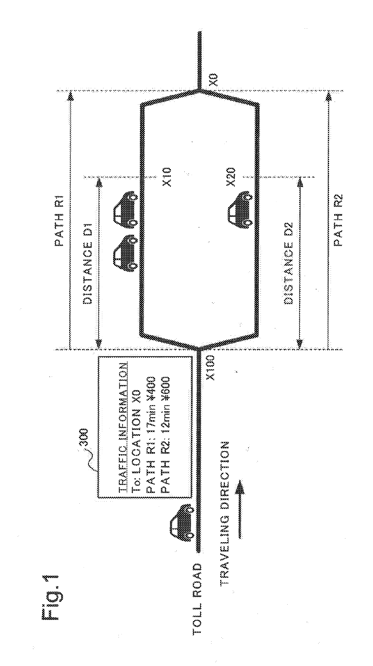
[0041]First, a road network to be controlled in the first example embodiment is described. In the first example embodiment, the road network to be controlled is a road network of a toll-way in which a passage toll (hereinafter, also simply described as a toll) is collected, and is capable of traffic dispersion by a plurality of paths.

[0042]FIG. 1 is a diagram illustrating an example of a road network to be controlled in the first example embodiment. As illustrated in FIG. 1, a location Xi for which a traffic state is to be monitored (i=0, 1, . . . , Nx−1; Nx is the number of locations to be monitored) is defined on a road. On a location X100, a path R1 or path R2 is selectable as a path to reach a location X0. Hereinafter, the location X100 is also referred to as a distribution location. Moreover, different tolls are settable for the path R1 and the path R2. A traffic state in each path is also monitored on the location X100.

[0043]...

second example embodiment

[0132]Next, a second example embodiment is described.

[0133]First, a road network to be controlled in the second example embodiment is described.

[0134]In the second example embodiment, the road network to be controlled is a road network including a toll-way in which a passage toll is collected, and a freeway in which a passage toll is not collected, and is capable of traffic dispersion between the toll-way and the freeway.

[0135]FIG. 13 is a diagram illustrating an example of the road network to be controlled in the second example embodiment. On a location X100, a toll-way (path R1) or a freeway (path R2) is selectable as a path to arrive at a location X0.

[0136]In the second example embodiment, a distribution ratio on the distribution location (location X100) is controlled in such a way that toll revenue of the toll-way (path R1) is maximized while a target service level is maintained in the toll-way. In the second example embodiment, the distribution ratio is controlled by changing a...

example embodiments

Characteristic Configuration of Example Embodiments

[0192]Next, a characteristic configuration according to the example embodiments is described.

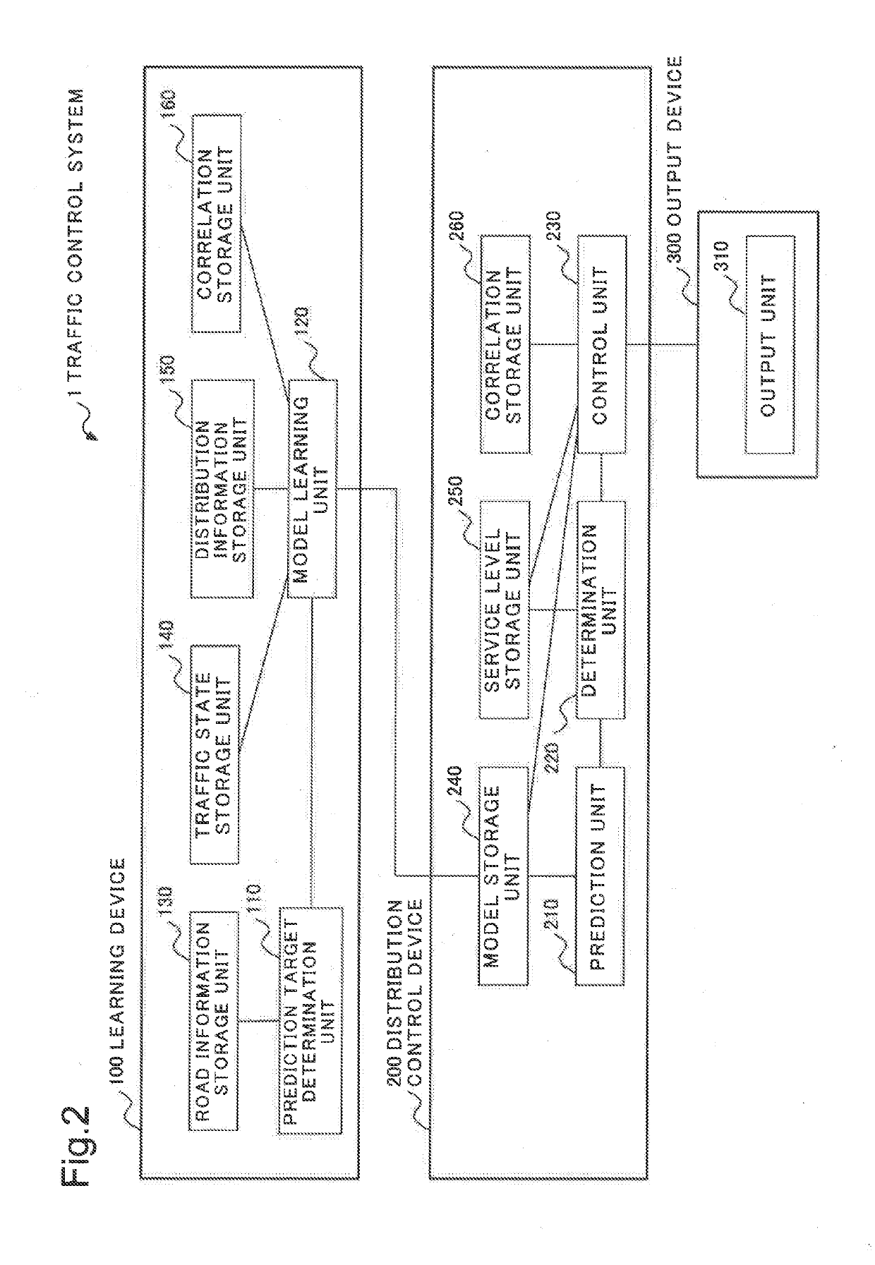
[0193]FIG. 19 is a block diagram illustrating a characteristic configuration according to the example embodiments.

[0194]Referring to FIG. 19, a traffic control system 1 includes a prediction unit 210 and a control unit 230. The prediction unit 210 predicts a traffic state on one path among a plurality of paths from a first location to a second location. The control unit 230 controls, when the traffic state predicted on the one path does not satisfy a predetermined service level, distributed numbers of vehicles among the plurality of paths on the first location in such a way that the traffic state on the one path satisfies the predetermined service level.

[0195]With this characteristic configuration, it is possible to obtain an advantageous effect that service quality provided by a toll-way can be maintained.

[0196]While the invention has been ...


PUM


Abstract

The purpose of the present invention is to preserve quality of service which a toll road provides. Provided is a traffic control system 1, comprising a prediction unit 210 and a control unit 230. The prediction unit 210 predicts a traffic state on one path among a plurality of paths from a first point to a second point. If the predicted traffic state on the one path does not satisfy a prescribed service level, the control unit 230 controls quantities of apportionment of vehicles among the plurality of paths on the first point such that the traffic state on the one path satisfies the prescribed service level.

Description

TECHNICAL FIELD[0001]The present invention relates to a traffic control system, a traffic information output device, a traffic control method, and a recording medium.BACKGROUND ART[0002]Traffic congestion is becoming particularly serious in urban areas where population growth is advancing. In most of the urban areas, toll-ways for avoiding and detouring the congested urban central part are provided. However, whether or not to actually utilize the detours depends on determination of drivers, and there is a strong tendency for each driver to select a shortest path. Thus, traffic dispersion by detours is not performed as expected, and unnecessary congestion is occurring. As a technique of easing such unnecessary congestion, there is disclosed a technique which guides vehicles to a detour by displaying current traffic states (congestion degrees, traveling times, and the like) of a main road and a detour, and discounts a passage toll of the detour. For example, PTL 1 describes a techniqu...

Claims


Application Information

Patent Timeline
Patent Type & Authority Applications(United States)
IPC IPC(8): G08G1/01
CPCG08G1/0145G08G1/0116G08G1/0129G08G1/0133G08G1/096811G06Q30/0207G06Q50/30G06Q10/047
Inventor NISHIOKA, ITARUASHIDA, YUTA
Owner NEC CORP
Why Eureka
Try Eureka