Method of managing buffer in radio network control equipment and radio network control equipment

a radio network control and radio network control technology, applied in the field can solve the problems of excessive load of mmux b>414/b> talking charge of the corresponding cell, waste of resources, and continuous transmission of error signals, so as to achieve the effect of effectively utilizing the processing capacity of mac layer multiplexer, improving service quality to users, and maintaining service quality

Inactive Publication Date: 2007-08-23
FUJITSU LTD
View PDF1 Cites 0 Cited by
  • Summary
  • Abstract
  • Description
  • Claims
  • Application Information

AI Technical Summary

Benefits of technology

[0035] Configuring the radio network control equipment as described above makes it possible to receive the burst of control signals with a proper restriction when the processing capacity of the MAC layer multiplexer has allowance, thereby achieving an improvement in service quality to users in the cell in which the burst is occurring as well as maintaining of the service quality to users in the other cells. As a result, it is possible to effectively utilize the processing capacity of the MAC layer multiplexer.

Problems solved by technology

However, when a failure occurs in a base transceiver station, erroneous signals may be continuously transmitted by the base transceiver station.
Accordingly, the MMUX 414 talking charge of the corresponding cell may have excessive loads.
However, it is wasteful to provide the excessive resources.

Method used


Image

  • Method of managing buffer in radio network control equipment and radio network control equipment
  • Method of managing buffer in radio network control equipment and radio network control equipment
  • Method of managing buffer in radio network control equipment and radio network control equipment

Examples


embodiments

[0077] Next, the configuration of radio network control equipment according to the invention will be described in detail.

[0078] Hereinafter, an embodiment of the invention will be described in detail on the basis of the drawings.

first embodiment

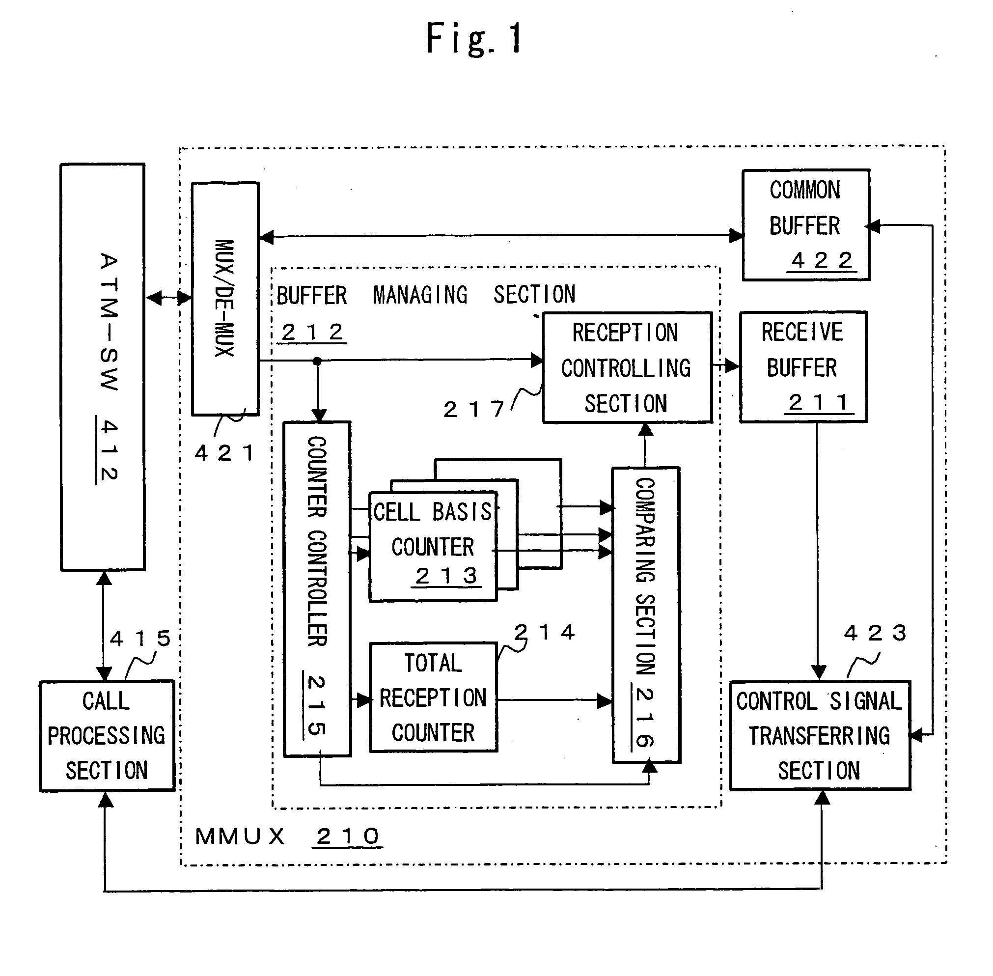
[0079]FIG. 1 is a block diagram of a MAC layer multiplexer according to an embodiment of the invention.

[0080] Among components shown in FIG. 1, the same parts with FIG. 4 are represented by the same reference numerals, and the descriptions thereof will be omitted.

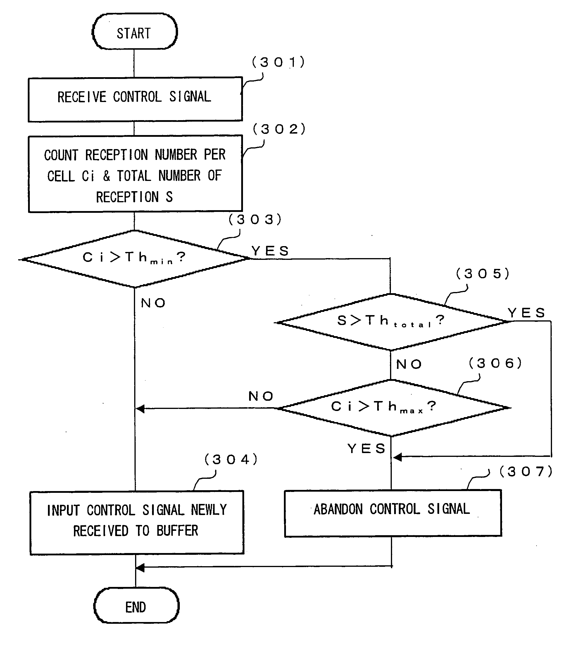
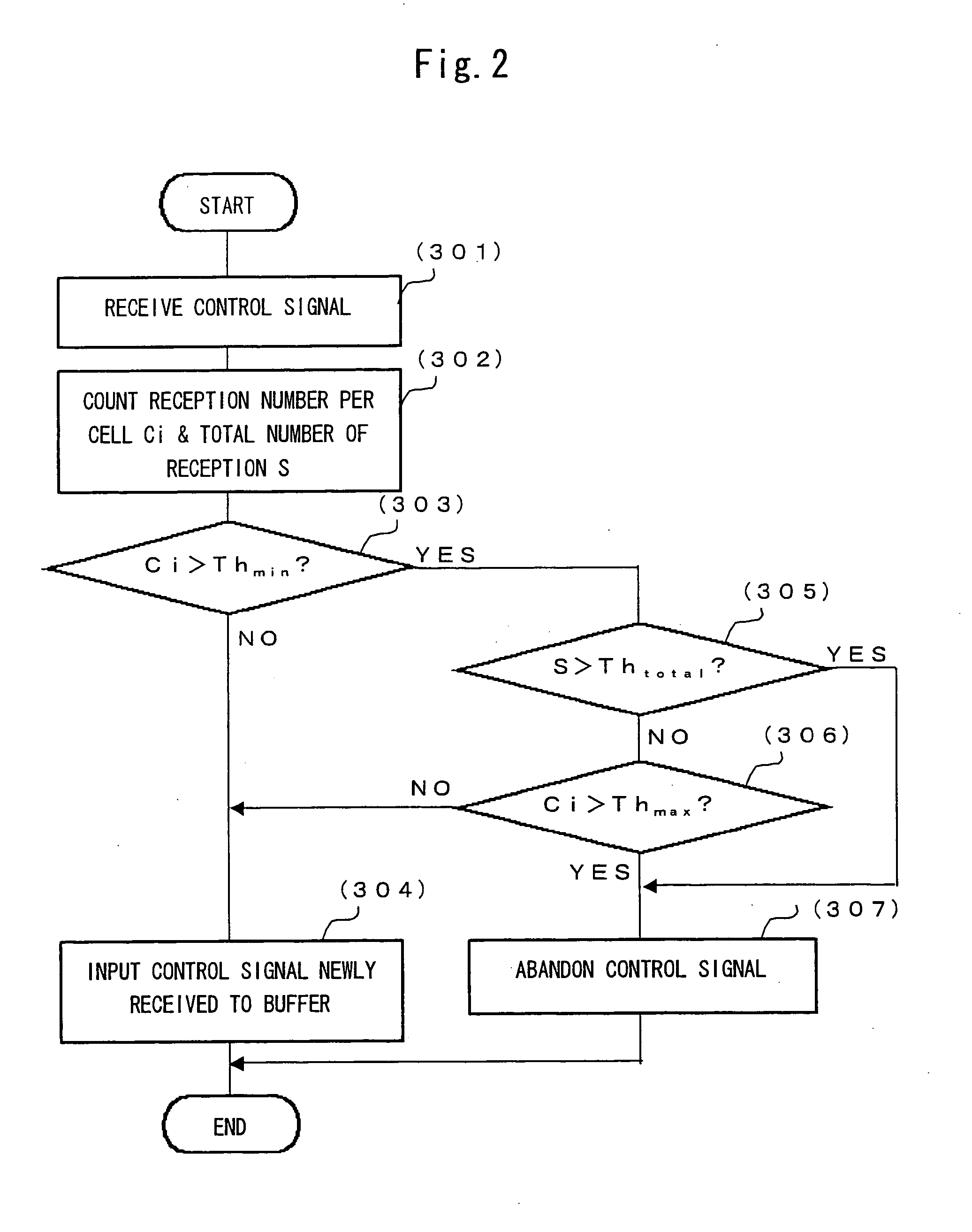
[0081] An MAC layer multiplexer (MMUX) 210 shown FIG. 1 includes a receive-only receive buffer 211 and a buffer managing section 212 which controls to input a control signal to the receive buffer 211 in addition to the common buffer 422 included in the MMUX 414 shown in FIG. 4.

[0082] The buffer managing section 212 shown in FIG. 1 includes a total reception counter 214 and a cell basis counter 213 provided so as to correspond to each of n number of cells assigned to the MMUX 210. The cell basis counter 213 and the total reception counter 214 perform a count operation in accordance with an indication from a counter controller 215.

[0083] Whenever a new control signal arrives in the MMUX 210, the counter controller 215 sho...


PUM


Abstract

Radio network control equipment is stably operated regardless of occurrence of burst of control signals by counting total number of control signals input to a buffer receiving control signals in each multiplexer in the radio network control equipment and the number of control signals transmitted from each cell in each unit time, comparing the total number of control signals with a device threshold determined in accordance with processing capacity of the multiplexer in the unit time, whenever a new control signal is input to each multiplexer, comparing the number of control signals transmitted from each cell with a guaranteed reception threshold which indicates reception number to be guaranteed for a single cell in the unit time, and determining to abandon the control signal or to input it to the buffer in every cell as a source of the new control signal on the basis of the comparison result.

Description

CROSS REFERENCE TO RELATED APPLICATION [0001] This application is based upon and claims the benefit of priority from Japanese Patent Application No. 2006-045489, filed on Feb. 22, 2006, the entire contents of which are incorporated herein by reference. BACKGROUND OF THE INVENTION [0002] 1. Field of the Invention [0003] The present invention relates to a MAC (Media Access Control) layer multiplexer included in radio network control equipment, in particular, to a technique for managing a reception load for control signals flowing through a plurality of base transceiver stations connected to radio network control equipment. [0004] 2. Description of the Related Art [0005]FIG. 4 shows an example of the configuration of radio network control equipment according to the related art. [0006] In the radio network control equipment shown in FIG. 4, an ATM switch 412 connects a base transceiver station interface 411 connected to each base transceiver station (BTS) under the radio network control...

Claims


Application Information

Patent Timeline
Patent Type & Authority Applications(United States)
IPC IPC(8): H04L12/26H04W28/14H04W88/12H04W88/14H04W92/00
CPCH04W88/12H04W28/14
Inventor SUGISAKI, HIDEYUKIMITA, SHINGO
Owner FUJITSU LTD
Why Eureka
Try Eureka