Apparatus and method for controlling transmission power

Active Publication Date: 2021-03-04
SAMSUNG ELECTRONICS CO LTD
View PDF0 Cites 3 Cited by
  • Summary
  • Abstract
  • Description
  • Claims
  • Application Information

AI Technical Summary

Benefits of technology

[0004]Exemplary embodiments of the present inventive concept provide a method and apparatus for maintaining qualit

Problems solved by technology

As such, heat and energy absorbed by a user of a wireless communicatio

Method used


Image

  • Apparatus and method for controlling transmission power
  • Apparatus and method for controlling transmission power
  • Apparatus and method for controlling transmission power

Examples


Example

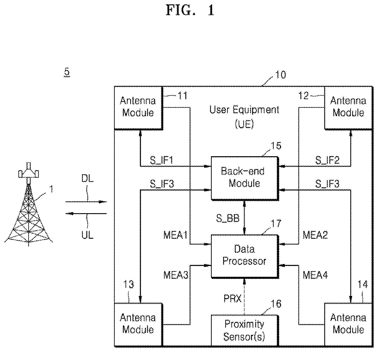
[0026]FIG. 1 shows a wireless communications system 5 according to an exemplary embodiment of the inventive concept. The wireless communications system 5 may include, but is not limited to, a wireless communications system using a cellular network such as, for example, a 5th-generation (5G) new radio (NR) system, a long term evolution (LTE) system, an LTE-advanced (LTE-A) system, a code-division multiple access (CDMA) system, a global system for mobile communications (GSM) system, a wireless personal area network (WPAN) system, or another arbitrary wireless communications system. The wireless communications system 5 will be described below on the basis of a 5G NR system as a wireless communications system using a cellular network, but embodiments of the inventive concept are not limited thereto.

[0027]A base station (BS) 1 may generally refer to a fixed station communicating with user equipment (UE) devices and / or other base stations, to communicate and exchange data and control info...


PUM


Abstract

An apparatus and method are provided for controlling a transmission power of a wireless communications device to comply with an output energy limit during a measurement period, including calculating a target output energy based on a communications channel; calculating a first average output energy corresponding to a previous period having a duration substantially equal to the measurement period; calculating a second average output energy by low-pass-filtering the target output energy and the first average output energy; and limiting the transmission power of the wireless communications device based on an energy margin between the output energy limit and the second average output energy.

Description

CROSS-REFERENCE TO RELATED APPLICATIONS[0001]This application claims priority under 35 U.S.C. § 119 to Korean Patent Application No. 10-2019-0108941, filed on Sep. 3, 2019 in the Korean Intellectual Property Office, the disclosure of which is incorporated by reference herein in its entirety.TECHNICAL FIELD[0002]Exemplary embodiments of the present inventive concept relate to wireless communications, and more particularly, to an apparatus and method for controlling transmission power.DISCUSSION OF RELATED ART[0003]Signal transmission in a wireless communications system may be affected by path loss, shadow fading, and the like, and thus sufficient power should be used to maintain quality of service (QoS). In particular, for wireless communications using easily attenuated high-frequency electromagnetic signals such as millimeter-wave (mmWave) signals, relatively high transmission power may be required to overcome such losses. However, when transmission power is increased, heat generate...

Claims


Application Information

Patent Timeline
IPC IPC(8): H04B1/3827H04W52/36H04W24/10H04W52/26
CPCH04B1/3838H04W52/265H04W24/10H04W52/367H04W52/225H04W52/228H04W52/28H04W52/146H04B7/0404
Inventor YU, HYUNSEOK
Owner SAMSUNG ELECTRONICS CO LTD
Why Eureka
Try Eureka