
Display device, backlight unit, light emitting module and lens

a technology of light emitting modules and display devices, which is applied in the direction of semiconductor devices for light sources, lighting and heating apparatus, instruments, etc., can solve problems such as interference of light emitted, and achieve the effect of minimizing or at least suppressing optical interferen

Active Publication Date: 2019-10-31
SEOUL SEMICONDUCTOR
View PDF0 Cites 0 Cited by
  • Summary
  • Abstract
  • Description
  • Claims
  • Application Information

AI Technical Summary

Benefits of technology

The invention is a display device, a backlight unit, a light emitting module, and a lens that can prevent optical interference between LEDs. This results in improved image quality and reduced blurring.

Problems solved by technology

Otherwise, interference of light emitted from each of the light emitting diodes may occur, which may generate shadows or partial hot spots.

Method used


Image

  • Display device, backlight unit, light emitting module and lens
  • Display device, backlight unit, light emitting module and lens
  • Display device, backlight unit, light emitting module and lens

Examples


Embodiment Construction

[0049]In the following description, for the purposes of explanation, numerous specific details are set forth in order to provide a thorough understanding of various exemplary embodiments or implementations of the invention. As used herein “embodiments” and “implementations” are interchangeable words that are non-limiting examples of devices or methods employing one or more of the inventive concepts disclosed herein. It is apparent, however, that various exemplary embodiments may be practiced without these specific details or with one or more equivalent arrangements. In other instances, well-known structures and devices are shown in block diagram form in order to avoid unnecessarily obscuring various exemplary embodiments. Further, various exemplary embodiments may be different, but do not have to be exclusive. For example, specific shapes, configurations, and characteristics of an exemplary embodiment may be used or implemented in another exemplary embodiment without departing from ...


PUM


Abstract

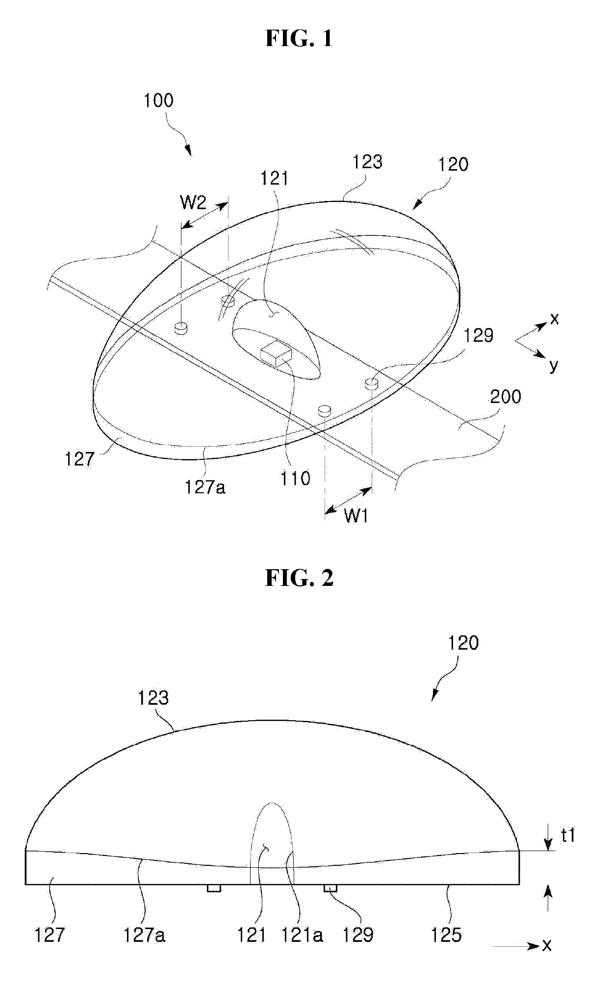
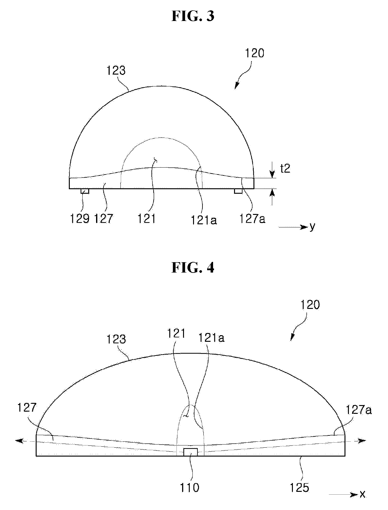
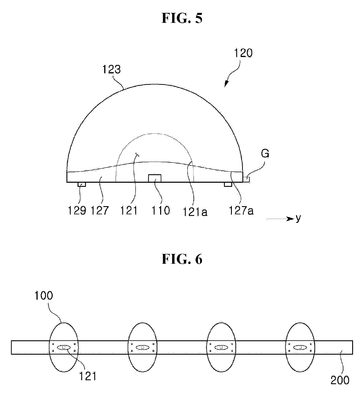
A lens including a light entering part having a concave shape in a lower region of the lens, and on which light emitted from a light emitting device is to be incident, and a light exiting part through which the incident light is emitted to the outside, in which each of the light entering part and the light exiting part has a major axis and a minor axis in plan view, and the major axis of the light entering part is orthogonal to the major axis of the light exiting part, and the light entering part includes a light incident vertical surface extending from a lower surface of the lens and a light incident inclined surface extending upward from the light incident vertical surface

Description

CROSS-REFERENCE TO RELATED APPLICATIONS[0001]This application is a Bypass Continuation of International Patent No. PCT / KR2018 / 002377, filed on Feb. 27, 2018, and claims priority from and the benefit of Korean Patent Application No. 10-2017-0026197, filed on Feb. 28, 2017, and Korean Patent Application No. 10-2018-0020302, filed on Feb. 21, 2018, each of which is hereby incorporated by reference for all purposes as if fully set forth herein.BACKGROUNDField[0002]Exemplary embodiments of the invention relate generally to a display device, a backlight unit, a light emitting module, and a lens, and more specifically, to a display device, a backlight unit, a light emitting module, and a lens capable of specifying a light emission distribution emitted to the outside.Discussion of the Background[0003]A light emitting diode is an inorganic semiconductor device, which emits light generated by recombination of electrons and holes. In recent years, light emitting diodes have been widely used in...

Claims


Application Information

Patent Timeline
Patent Type & Authority Applications(United States)
IPC IPC(8): F21V5/04H01L33/58H01L25/075
CPCH01L33/58H01L25/0753F21V5/04F21Y2115/10H01L2933/0058G02B19/0066G02F1/133603G02F1/133606G02F1/133607
Inventor KIM, EUN JUPARK, JAE EUN
Owner SEOUL SEMICONDUCTOR
Learn More