
Balancing arrangement for minimizing bending stress in a power cutter arm

a technology of balancing arrangement and power cutter, which is applied in the direction of manufacturing tools, machines/engines, and portable power-driven tools, etc., can solve the problems of high unbalance force of crank webs, different strain situations of cutter arms, and a large amount of abrasive particulate matter, so as to minimize or reduce bending stress and simple design

Active Publication Date: 2014-01-21
HUSQVARNA AB
View PDF5 Cites 0 Cited by
  • Summary
  • Abstract
  • Description
  • Claims
  • Application Information

AI Technical Summary

Benefits of technology

The objective of the patent is to provide a solution to reduce bending stress in a cutter arm, especially during engine speed that matches a bending resonance frequency. The solution should be simple and low-weight. This is important because bending stress can cause damage and limit the performance of the cutter arm. The goal is to make it more efficient and durable.

Problems solved by technology

Such a cutting creates a lot of abrasive particulate matter.
A result of all these differences is that the unbalance forces and torques created by the single cylinder engine gives a very different, more complex and more severe strain situation for the cutter arm.
This creates high unbalance forces from the crank webs.
Also it is only possible to balance in a direction perpendicular to the cylinder axis, as the unbalance forces act in this direction.
As the cutter arm normally does not run in this direction, such a balancing system can not minimize bending stress in the cutter arm, and the purpose was to reduce handle vibrations.
Further this type of balancing creates extra weight in the crank webs and extra weight in a flywheel or clutch for compensating the extra weight in the crank webs.
This is a disadvantage for a hand held machine.
Therefore it is only possible to balance in a direction perpendicular to the cylinder axis, as the unbalance forces act in this direction.
As the cutter arm normally does not run in this direction, such a balancing system can not minimize bending stress in the cutter arm, but could of course reduce vibrations in the handles.
So the recommendations of this document did not and can not solve the problem of reducing cutter arm fatigue, in fact it teaches away from a solution.

Method used


Image

  • Balancing arrangement for minimizing bending stress in a power cutter arm
  • Balancing arrangement for minimizing bending stress in a power cutter arm
  • Balancing arrangement for minimizing bending stress in a power cutter arm

Examples


Embodiment Construction

[0026]The present invention will be described more fully hereinafter with reference to the accompanying drawings, in which example embodiments of the invention incorporating one or more aspects of the present invention are shown. This invention may, however, be embodied in many different forms and should not be construed as limited to the embodiments set forth herein; rather, these embodiments are provided so that this disclosure will be thorough and complete, and will fully convey the scope of the invention to those skilled in the art. For example, one or more aspects of the present invention can be utilized in other embodiments and even other types of devices. In the drawings, like numbers refer to like elements.

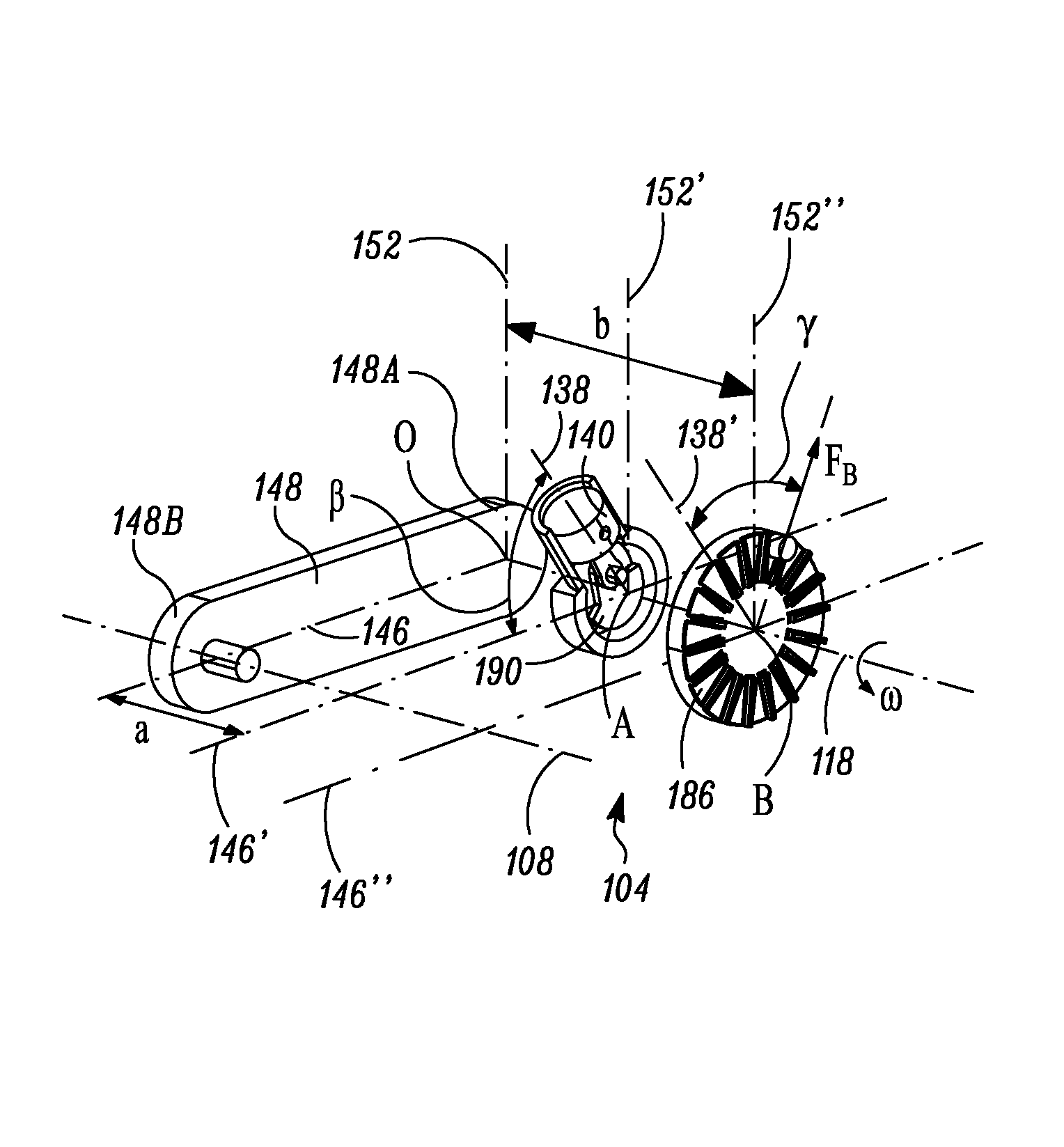
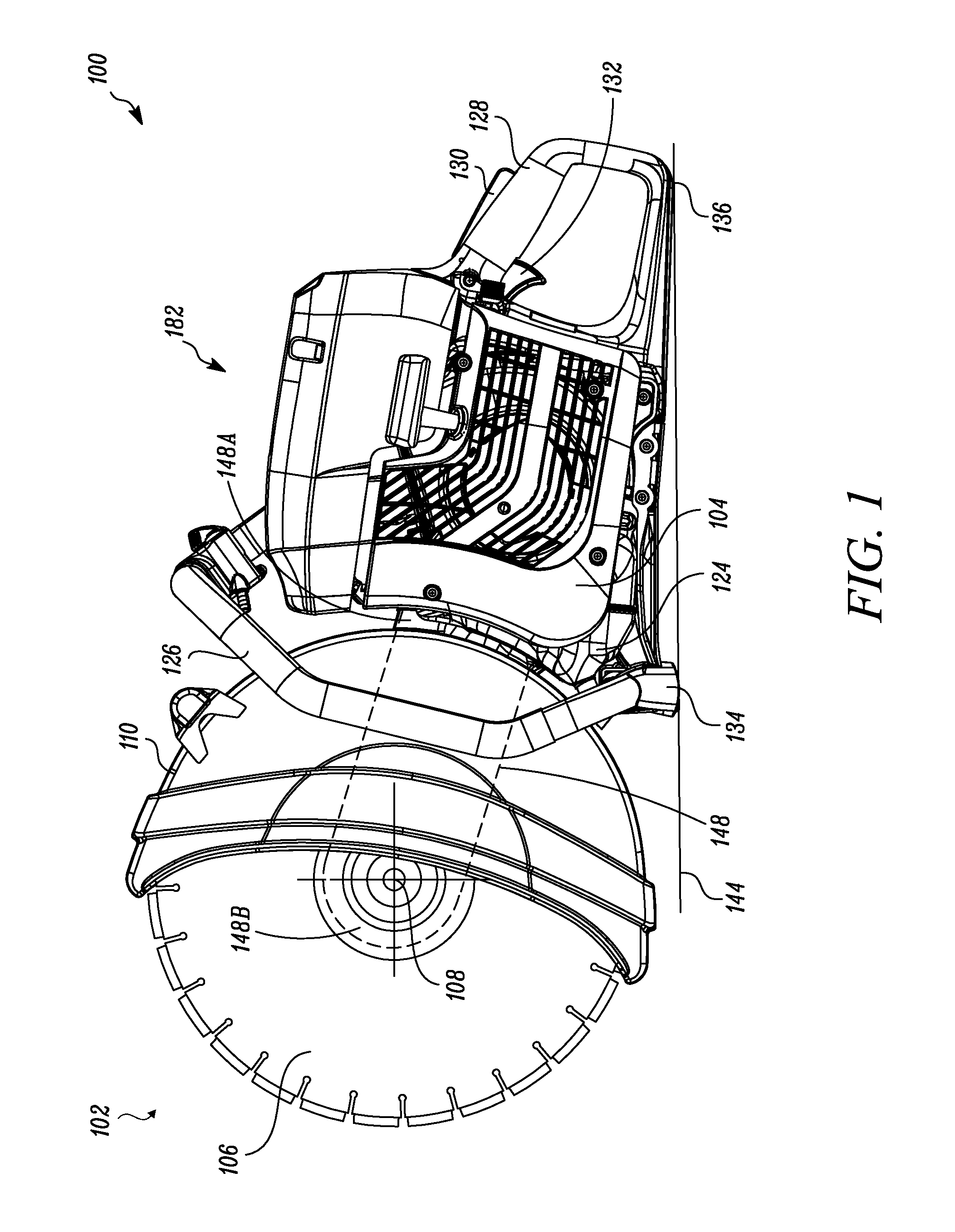
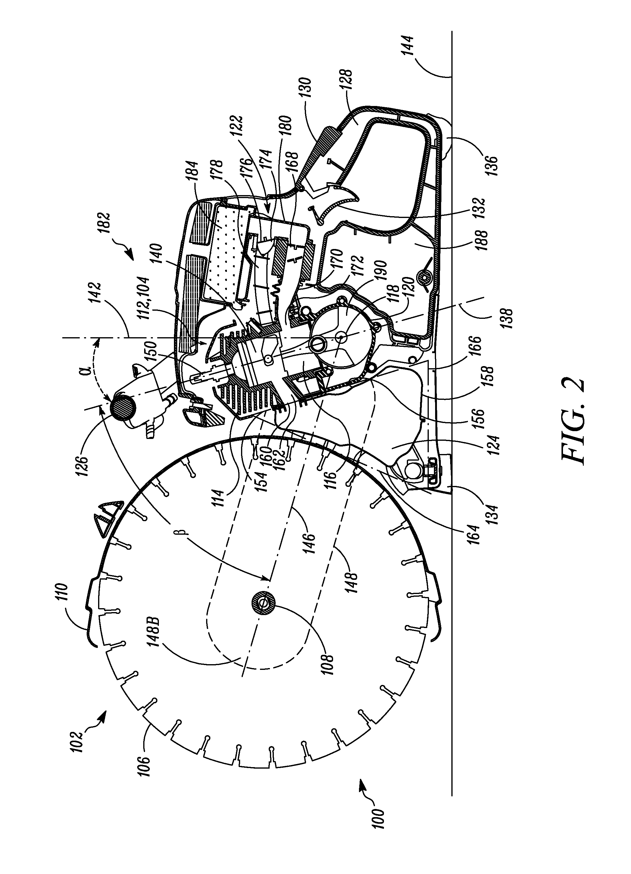
[0027]FIGS. 1 and 2 show an example portable hand-held power cutter 100 incorporating some aspects of the present invention.

[0028]The power cutter 100 may includes a tool unit 102 and a drive unit 104. The tool unit 100 is provided with a working tool 106. In an embodiment...


PUM


Abstract

A power cutter powered by a single cylinder internal combustion engine, the power cutter including: a tool unit having at least one tool, which can be rotated about an axis of rotation; a drive unit including an engine, the engine including an engine cylinder having a cylinder bore centerline, a piston, a crankshaft with a crankshaft axis of rotation and a flywheel, the crankshaft running in a counter clockwise direction as seen towards the flywheel; a cutter arm attached to the drive unit in its inner end and its outer end carrying the tool unit, a centerline of the cutter arm essentially follows a connection line between the axis of rotation of the tool and the axis of rotation of the crankshaft.

Description

CROSS-REFERENCE TO RELATED APPLICATIONS[0001]This application is a national stage entry of PCT / SE2010 / 051289, which was filed on Nov. 23, 2010, said application is expressly incorporated herein in its entirety.TECHNICAL FIELD[0002]The present invention relates to a power cutter powered by a single cylinder internal combustion engine. The power cutter comprising: a tool unit having at least one working tool, which can be rotated about an axis of rotation, and preferably having a tool guard;[0003]a drive unit comprising a single cylinder internal combustion engine, the engine comprising an engine cylinder with cylinder bore having a cylinder bore centerline, a piston, a crankshaft with at least one crank web and a crankshaft axis of rotation, a crankcase, a muffler and a flywheel, the crankshaft running in a counter clockwise direction as seen towards the flywheel;[0004]a cutter arm attached to the drive unit in its inner end and its outer end carrying the tool unit, a centerline of t...

Claims


Application Information

Patent Timeline
Patent Type & Authority Patents(United States)
IPC IPC(8): F02B75/06
CPCF01N1/00F01N2340/04B23D45/16F02B63/02F16F15/26F01N2590/06B25F5/02B28D1/04B23D47/12F02B75/06F01N13/002F01N13/1888F01N2260/022
Inventor PETERSSON, HANSHOLMDAHL, MATTIASLUNDGREN, ANDERS
Owner HUSQVARNA AB
Learn More