
Containment unit and method of using same

a technology of containment unit and container, which is applied in the field of containment unit, can solve the problems of monetary expense and environmental cost of these spills, huge environmental problems, and large amount of oil wastage, and achieve the effect of minimizing or even eliminating any environmental clean-up cos

Inactive Publication Date: 2014-01-23
MARQUIX
View PDF6 Cites 0 Cited by
  • Summary
  • Abstract
  • Description
  • Claims
  • Application Information

AI Technical Summary

Benefits of technology

The invention is a reusable device that captures oil spills and allows them to be harvested while minimizing or eliminating environmental clean-up costs. This device is designed to contain oil spills and keep them in one area, making it easier to manage and dispose of.

Problems solved by technology

It has long been known that such leaks waste valuable quantities of oil and / or gas, and the oil causes huge environmental problems, both to the sea, beaches, wildlife, etc.
The monetary expense and cost to the environment of these spills is staggering.
Great quantities of oil wastage are involved with these spills.
However, the spill continues to cause extensive damage to marine and wildlife habitats as well as the Gulf's fishing and tourism industries.

Method used


Image

  • Containment unit and method of using same
  • Containment unit and method of using same
  • Containment unit and method of using same

Examples


first embodiment

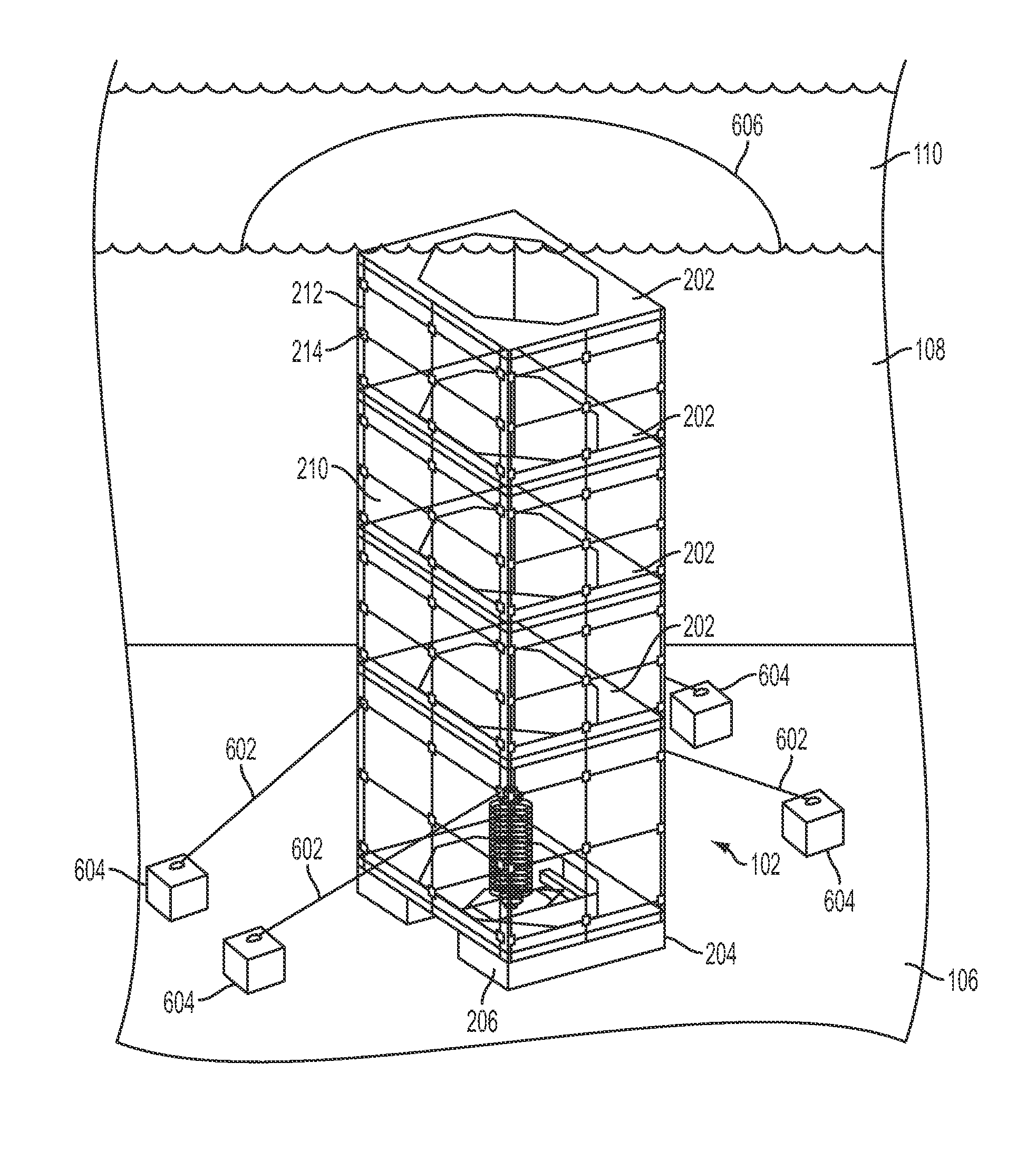
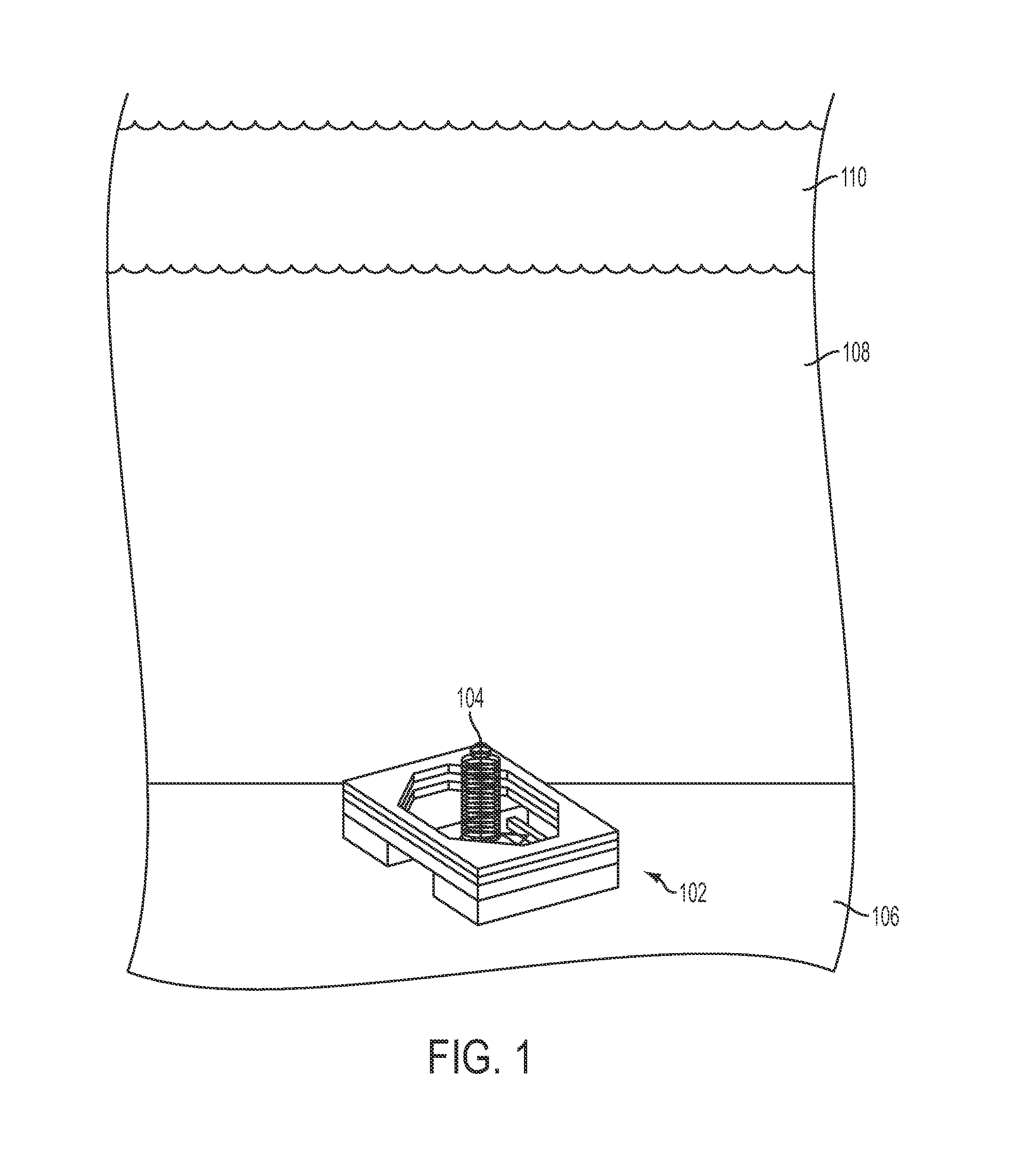
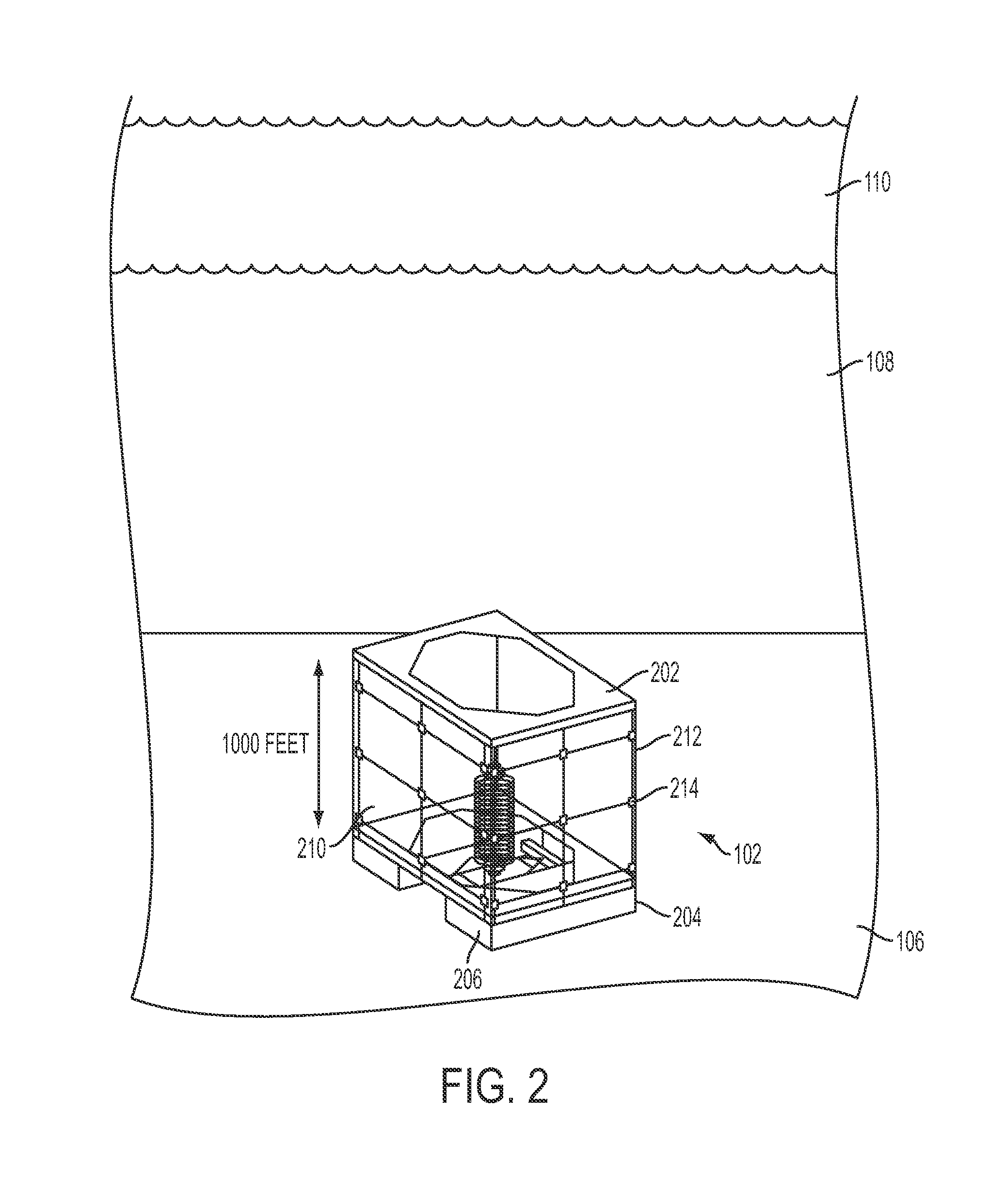
[0034]The containment unit of the first embodiment is preferably made up of 4 flotation units and 1 anchor unit. Each flotation unit preferably has an inside diameter of 30×30 feet to accommodate a broken / damaged riser and Kevlar walls reinforced with rubber coated iron cables for frame support. The base unit is 2 to 4 tons and 20 feet high depending on the water depth. The containment unit may also be square, rectangle, oval or round.

[0035]The walls are preferably made of a layer of Kevlar with a rubber coated cable frame and then another coat of Kevlar for added strength. When attached to the flotation units that will become the containment unit, the cables comprise 20,000 feet of Kevlar and cable frame. Each flotation unit will rise 1,000 feet. While Kevlar is given as an illustrative example, any other suitable material can be used, as long as it is impermeable to oil, flexible, and not broken down by oil or salt water. Kevlar is considered a good choice because it can withstand...

second embodiment

[0049]The structure of the second embodiment provides:[0050]A sturdy concrete base that can be preinstalled before disaster strikes;[0051]A quick response deep sea containment structure;[0052]A safe solution to containment and control of an oil spill caused by a damaged or faulty piece of subsea equipment in deepwater situations;[0053]A cost effective method to contain oil spills to a specific location; and[0054]The ability to harvest the oil as it flows to the top at the water surface, minimizing impact on the environment.

[0055]In either of the preferred embodiments, or in any other embodiment, variations on the flotation device are possible. For example, lift bags can be used for quick erection, and the flotation units are then used to keep the containment unit upright and erected. Although foam is preferred for the flotation units because of its stability for long-term deployment in various environments, other suitable materials as would be known to one of skill in the art may al...


PUM


Abstract

The present invention generally relates to containment and control of an oil spill caused by a damaged or broken riser in deepwater. More specifically, the present invention relates to a reusable unit that will contain oil spills to a specific location and will also allow oil to be harvested as it flows to the top of the unit while minimizing or even eliminating any environmental clean-up cost. The unit of the present invention is dropped over a damaged or broken riser in a closed positin, the unit is released and stabilized in sections until the surface is reached and the containment unit is completely erected.

Description

REFERENCE TO RELATED APPLICATION[0001]The present application is a continuation-in-part of U.S. Provisional Patent Application No. 61 / 439,352, filed Feb. 3, 2011, whose disclosure is hereby incorporated by reference in its entirety into the present disclosure.FIELD OF INVENTION[0002]The present invention relates to oil leaks under water (or similar situations such as gas leaks on land) and means of containing and recovering spilled oil, quickly, efficiently and conveniently thereby minimizing loss of oil and protecting the environment.BACKGROUND OF INVENTION[0003]For years, the problem of salvaging deep sea oil leaks has been of great concern. It has long been known that such leaks waste valuable quantities of oil and / or gas, and the oil causes huge environmental problems, both to the sea, beaches, wildlife, etc. The monetary expense and cost to the environment of these spills is staggering.[0004]Great quantities of oil wastage are involved with these spills. For example, in the 197...

Claims


Application Information

Patent Timeline
IPC IPC(8): E02B15/04
CPCE02B15/045B63B27/34B63C7/006E21B43/0122E02B15/0857E02B2015/005E02D2220/00
Inventor COOK, RONALD
Owner MARQUIX
Learn More