Method for performing uninterruptible power distribution work within section in de-energized line state by separating wires within pole-to-pole span by means of insulated live wire grip and bypass jumper cable

Inactive Publication Date: 2019-10-31
DAEWON ELECTRONICS CO LTD +2
View PDF0 Cites 1 Cited by
  • Summary
  • Abstract
  • Description
  • Claims
  • Application Information

AI Technical Summary

Benefits of technology

[0038]As is apparent from the above description, an uninterruptible power distribution method for performing in-section work in a dead-line state by separating an electric wire within a pole-to-pole span using an insulated live-line wire grip and a bypass jumper wire according to the present invention has the following effects. In the case in which uninterruptible work is performed using a conventional bypass cable work method in the state in which dead-line preparation work is completed, except for uninterruptible work at a work-section start electric pole and a work-section end electric pole at a work site, a bypass cable is laid in order to perform uninterruptible work for safety even in a section in which the preparation of work has already been completed, which reduces work efficiency and site utilization efficiency. According to the present invention, however, it is possible to remarkably reduce safety-related accidents that occur as the result of immoderate direct live-line uninterruptible work performed at a work-section start electric pole and a work-section end electric pole

Problems solved by technology

As the level of electric power consumers' demand for high-quality electrical service increases, instantaneous electric power failure has become a target of public grievance.
That is, an uninterruptible power distribution method is used.
In this case, however, there are many temporary connection points that are unstable, for example, due to voltage drop.
As a result, excessive time is required to perform incidental work.
In the case in which an uninterruptible power distribution method using an electric wire relocation tool and additional direct live-line work are performed, three live-line electric wires and three dead-line electric wires are provided in a mixed state when the electric wires are stretched and tensioned at opposite sides of a work section, whereby safet

Method used


Image

  • Method for performing uninterruptible power distribution work within section in de-energized line state by separating wires within pole-to-pole span by means of insulated live wire grip and bypass jumper cable
  • Method for performing uninterruptible power distribution work within section in de-energized line state by separating wires within pole-to-pole span by means of insulated live wire grip and bypass jumper cable
  • Method for performing uninterruptible power distribution work within section in de-energized line state by separating wires within pole-to-pole span by means of insulated live wire grip and bypass jumper cable

Examples


Example

Embodiment 1

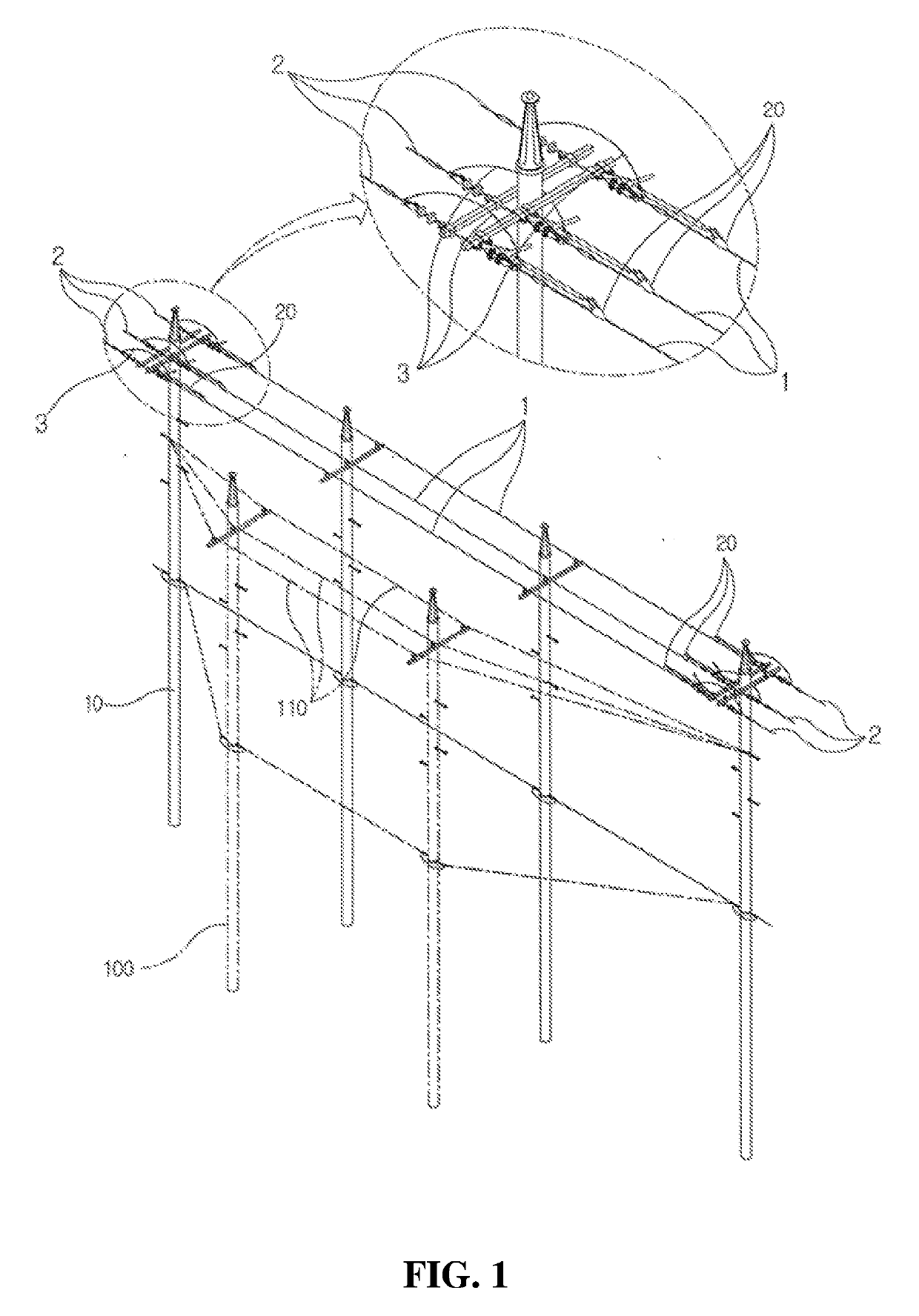
[0089]The case in which electric pole relocation work, electric pole replacement work, and electric pole route change work are performed, as shown in FIG. 1

[0090]When electric pole relocation work, electric pole replacement work, and electric pole route change work are performed in an uninterruptible state, electric-pole establishment work, electric-pole assembly work, and electric wiring work are performed within a work section in a dead-line state, except for uninterruptible work at a work-section start electric pole and a work-section end electric pole, in order to perform uninterruptible preparation work, whereby preparation to perform uninterruptible work is achieved.

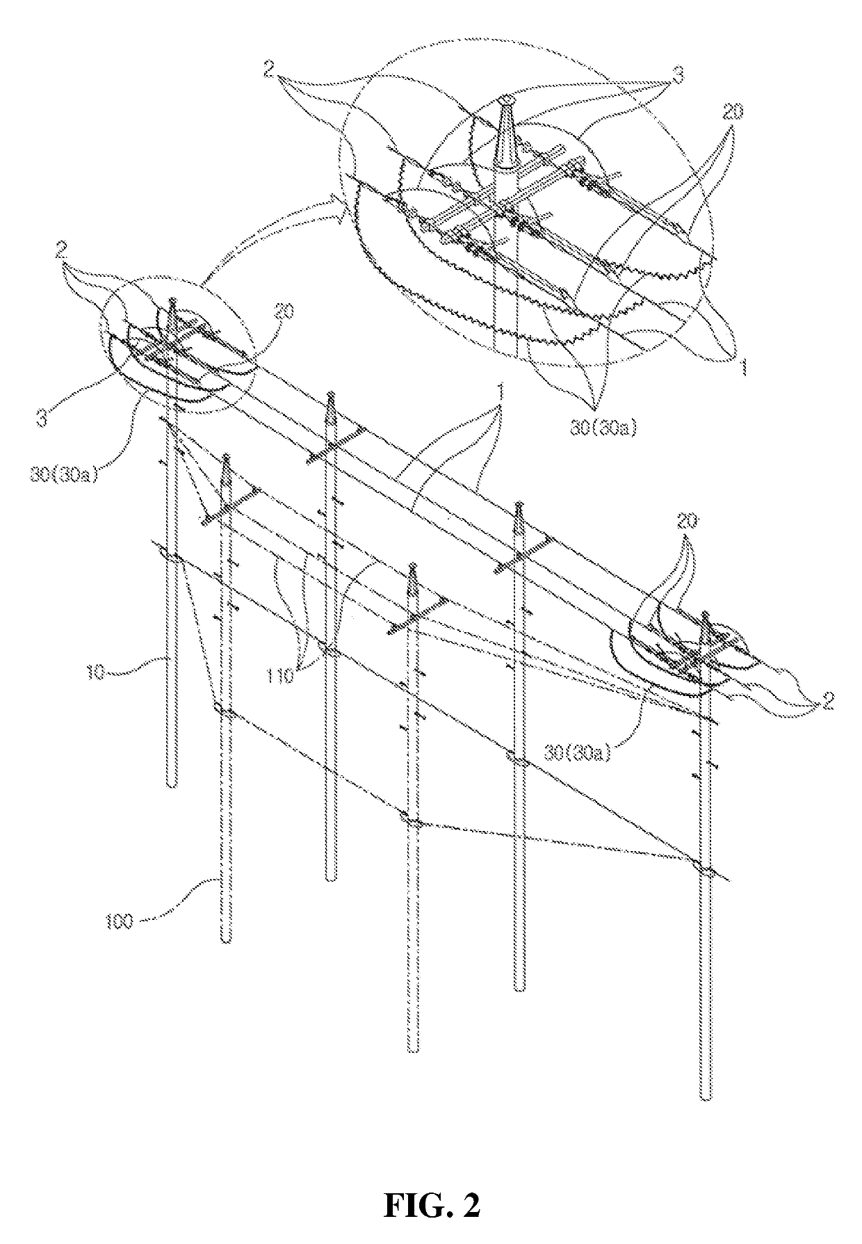
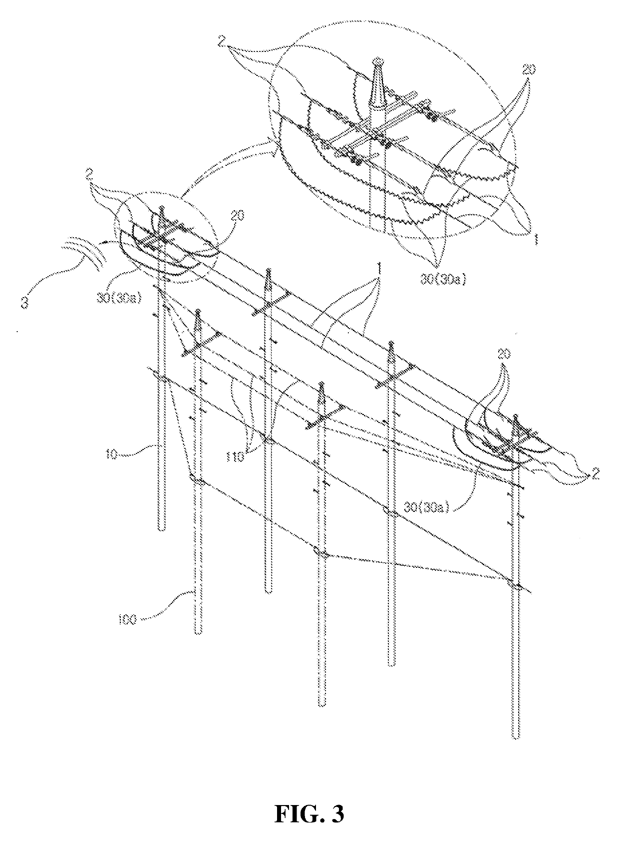
[0091]At this time, when the uninterruptible work is performed, as shown in FIG. 2, electric wire clips of insulated live-line wire grips 20 for holding the tension of electric wires are installed inside a work section defined by a work-section start electric pole 10 and a work-section end electric pole...

Example

Embodiment 2

[0093]The case in which a branch-line electric pole 100a is present within a work section, as shown in FIG. 7

[0094]Electric-pole establishment work, electric-pole assembly work, and electric wiring work are performed within a work section in a dead-line state in order to perform uninterruptible preparation work, and, as shown in FIG. 7, electric wire clips of insulated live-line wire grips 20 for holding the tension of electric wires are installed inside a work section defined by a work-section start electric pole 10 and a work-section end electric pole 10 at points at which a safe dead-line work section of electric wires to be removed is secured. After the installation is completed, as shown in FIG. 8, one end of a bypass jumper means 30 is connected to an electric wire outside each of the electric wire clips of the insulated live-line wire grips 20 within the work section span, and the other end of the bypass jumper means 30 is connected to an electric wire located out...

Example

Embodiment 3

[0098]The case in which an electric pole 10b having a pole-mounted transformer is present within a work section, as shown in FIG. 13

[0099]Electric-pole establishment work, electric-pole assembly work, and electric wiring work are performed within a work section in a dead-line state in order to perform uninterruptible preparation work, and, as shown in FIG. 13, electric wire clips of insulated live-line wire grips 20 for holding the tension of electric wires are installed inside a work section defined by a work-section start electric pole 10 and a work-section end electric pole 10 at points at which a safe dead-line work section of electric wires to be removed is secured. After the installation of the insulated live-line wire grips 20 is completed, as shown in FIG. 14, one end of a bypass jumper means 30 is connected to an electric wire outside each of the electric wire clips of the insulated live-line wire grips 20 within the work section span, and the other end of the b...


PUM


Abstract

Provided is a method for performing uninterruptible power distribution work within a working section in a de-energized line state by separating wires within a pole-to-pole span by means of an insulated live wire grip and a bypass jumper cable, wherein: uninterruptible power distribution work can be forcibly performed directly on a live wire between poles located at the beginning and end of a working section without installing a bypass cable at the work site, and the work process employs a direct power transmission method in which power distribution work is performed by bypassing new and old wires, whereby, even when transformers are located at several points within a working section, uninterruptible power distribution work can be performed via one uninterruptible transformer apparatus by using, as the interruptible power distribution method.

Description

TECHNICAL FIELD[0001]The present invention relates to an uninterruptible power distribution method in a distribution line, and more particularly to an uninterruptible power distribution method for performing in-section work in a dead-line state by separating an electric wire within a pole-to-pole span using an insulated live-line wire grip and a bypass jumper wire that is capable of being performed in a wide variety of conditions at a work site when uninterruptible work is performed while preventing safety-related accidents due to immoderate work and preventing the congestion of traffic at the work site due to excessive input of equipment and manpower, thereby improving work efficiency.BACKGROUND ART[0002]With the rapid increase in the demand for electric power, electric power equipment corresponding thereto has been continuously enlarged. As the level of electric power consumers' demand for high-quality electrical service increases, instantaneous electric power failure has become a...

Claims


Application Information

Patent Timeline
IPC IPC(8): H02G1/02H02G7/05H02G1/00
CPCH02G1/02H02G1/005H02G7/053H02G7/20H02G7/02
Inventor KWON, SAE WON
Owner DAEWON ELECTRONICS CO LTD
Why Eureka
Try Eureka