
Hydraulic valve torque motor air gap measurement and performance debugging method

A technology of torque motor and debugging method, which is used in fluid pressure actuation system testing, mechanical valve testing, fluid pressure actuating device and other directions, can solve the problem that there is no clear detection and debugging method, the detection method is difficult to meet the requirements, and the requirements are relatively harsh. and other problems, to achieve the effect of improving efficiency and economy, low cost and simple detection method

Active Publication Date: 2021-06-22
TONGJI UNIV
View PDF8 Cites 0 Cited by
  • Summary
  • Abstract
  • Description
  • Claims
  • Application Information

AI Technical Summary

Problems solved by technology

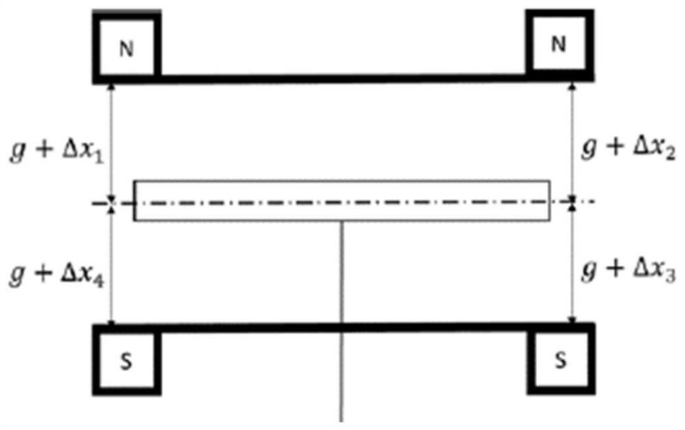
[0004] Literature (Fu Yaobao, Li Cong, Li Changming, Lu Liang. Influence of torque motor air gap error on electro-hydraulic servo valve bias[J]. Journal of Huazhong University of Science and Technology (Natural Science Edition), 2019,47(03):55 -61.) The influence of the air gap error of the torque motor on the zero deviation of the electro-hydraulic servo valve is analyzed. The requirements for key dimensions in the electro-hydraulic servo valve and electro-hydraulic proportional valve are relatively strict. For example, the working air gap length of the torque motor is only a few 100 microns, and the allowable error is only a few microns. The air gap error of the torque motor is closely related to its performance, but conventional detection methods are difficult to meet this requirement. Among the torque motors, there is no clear and written detection and debugging method
At present, most technicians detect and debug torque motor performance based on experience, intuition, and lack of professionalism

Method used


Image

  • Hydraulic valve torque motor air gap measurement and performance debugging method
  • Hydraulic valve torque motor air gap measurement and performance debugging method
  • Hydraulic valve torque motor air gap measurement and performance debugging method

Examples


Embodiment Construction

[0040] The present invention will be described in detail below with reference to the drawings and specific embodiments. Apparently, the described embodiments are part of the embodiments of the present invention, not all of them. Based on the embodiments of the present invention, all other embodiments obtained by persons of ordinary skill in the art without making creative efforts shall fall within the protection scope of the present invention.

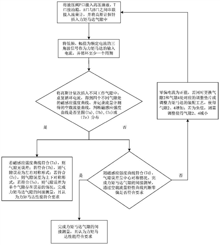
[0041] The invention provides a hydraulic valve torque motor air gap measurement and performance debugging method, such as figure 1 As shown, the main steps of the method are as follows:

[0042]Step 1: The P port of the hydraulic valve is connected to the high-pressure oil, the T port is connected to the oil tank, and the flowmeter is connected in series between the A port and the B port;

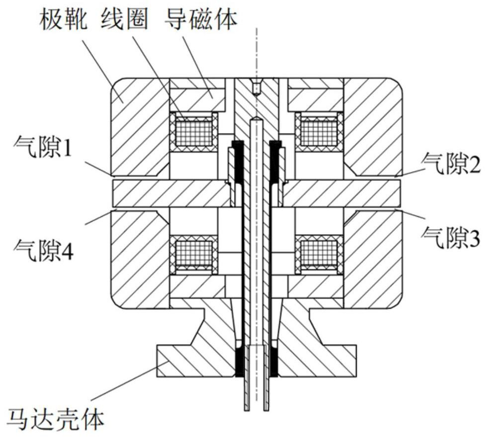
[0043] Step 2: Insert the gauss meter probe into the air gap of the torque motor, and measure the magnetic induction at the air gap;

[0044] St...


PUM


Abstract

The invention relates to a hydraulic valve torque motor air gap measurement and performance debugging method. The method comprises the following steps: 1) connecting a port P of a hydraulic valve with high-pressure oil, connecting a port T with an oil tank, and serially connecting a flowmeter to the space between a port A and a port B; 2) taking a low-frequency triangular wave signal with the amplitude being rated current as input current of a torque motor; 3) during the working process of the hydraulic valve, acquiring a hydraulic valve no-load flow characteristic curve in a complete cycle period, sequentially inserting gauss meters in different working air gaps, and repeatedly circulating the current to obtain magnetic induction intensity curves at four air gaps; and 4) according to the distribution condition of the magnetic induction intensity curve at each air gap, judging the air gap error form of the corresponding air gap, judging whether zero offset meets requirements in combination with the hydraulic valve no-load flow characteristic curve, adjusting each air gap of the torque motor, and completing performance debugging. Compared with the prior art, the measurement method of the invention is simple, and has the advantages of good operability, high accuracy and high efficiency.

Description

technical field [0001] The invention relates to the technical field of hydraulic valve performance detection, in particular to a hydraulic valve torque motor air gap measurement and performance debugging method. Background technique [0002] Hydraulic valves, including electro-hydraulic servo valves and electro-hydraulic proportional valves, have significant advantages such as high control precision, fast response, small size, light weight, and high power amplification factor, and have been widely used in aerospace, military, ship, and industrial fields. , the electro-hydraulic servo valve and the electro-hydraulic proportional valve are the core components of the hydraulic control system, which have high requirements for precision, which brings about the increase of detection and maintenance costs. The assembly of the electro-hydraulic servo valve and the electro-hydraulic proportional valve involves many The cooperation of precise parts and the inevitable errors of each pa...

Claims


Application Information

Patent Timeline
IPC IPC(8): F15B19/00G01R33/02G01M13/003
CPCF15B19/002F15B19/007G01R33/02G01M13/003Y02E10/20
Inventor 訚耀保郭文康
Owner TONGJI UNIV
Learn More