Exoskeleton structure that provides force assistance to the user

Active Publication Date: 2019-11-07
SAFRAN ELECTRONICS & DEFENSE +1
View PDF7 Cites 2 Cited by
  • Summary
  • Abstract
  • Description
  • Claims
  • Application Information

AI Technical Summary

Benefits of technology

[0009]One goal of the invention is to propose a solution for relieving the user of the loads which he carries, whether the load generated by the structure of the exoskeleton itself, by e

Problems solved by technology

In the case of exoskeletons designed for assisting the movements of the user, the user must generally transport the structure of the exoskeleton because it is disposed on his body, which has the consequence of limiting the freedom of movement of the user and of generating an additional load and associated fatigue.
In these structures, the feet of the user are not in contact with the ground, which makes the structure uncomfortable.
Moreover, due to the presence of the p

Method used


Image

  • Exoskeleton structure that provides force assistance to the user
  • Exoskeleton structure that provides force assistance to the user
  • Exoskeleton structure that provides force assistance to the user

Examples


first embodiment

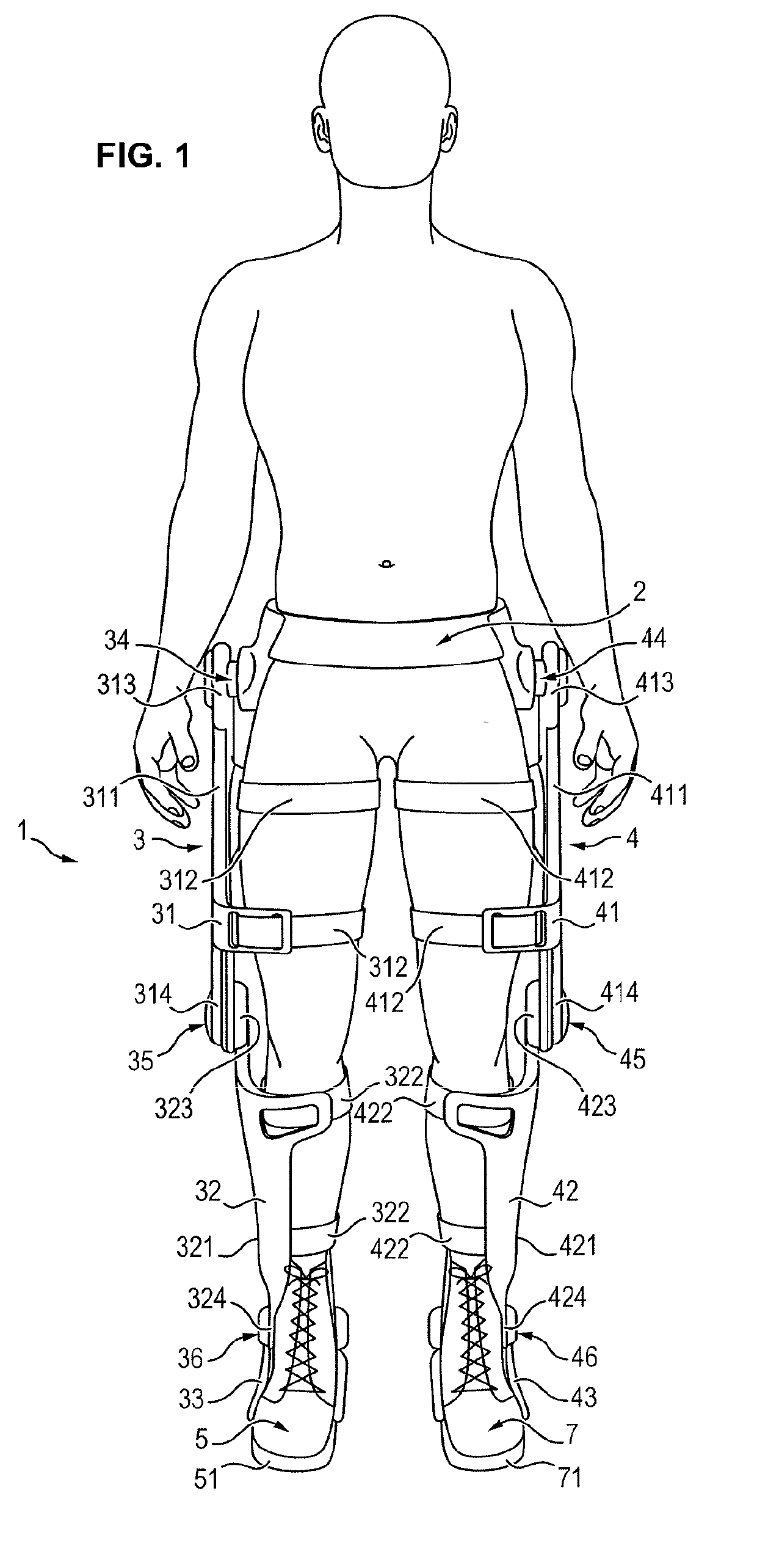
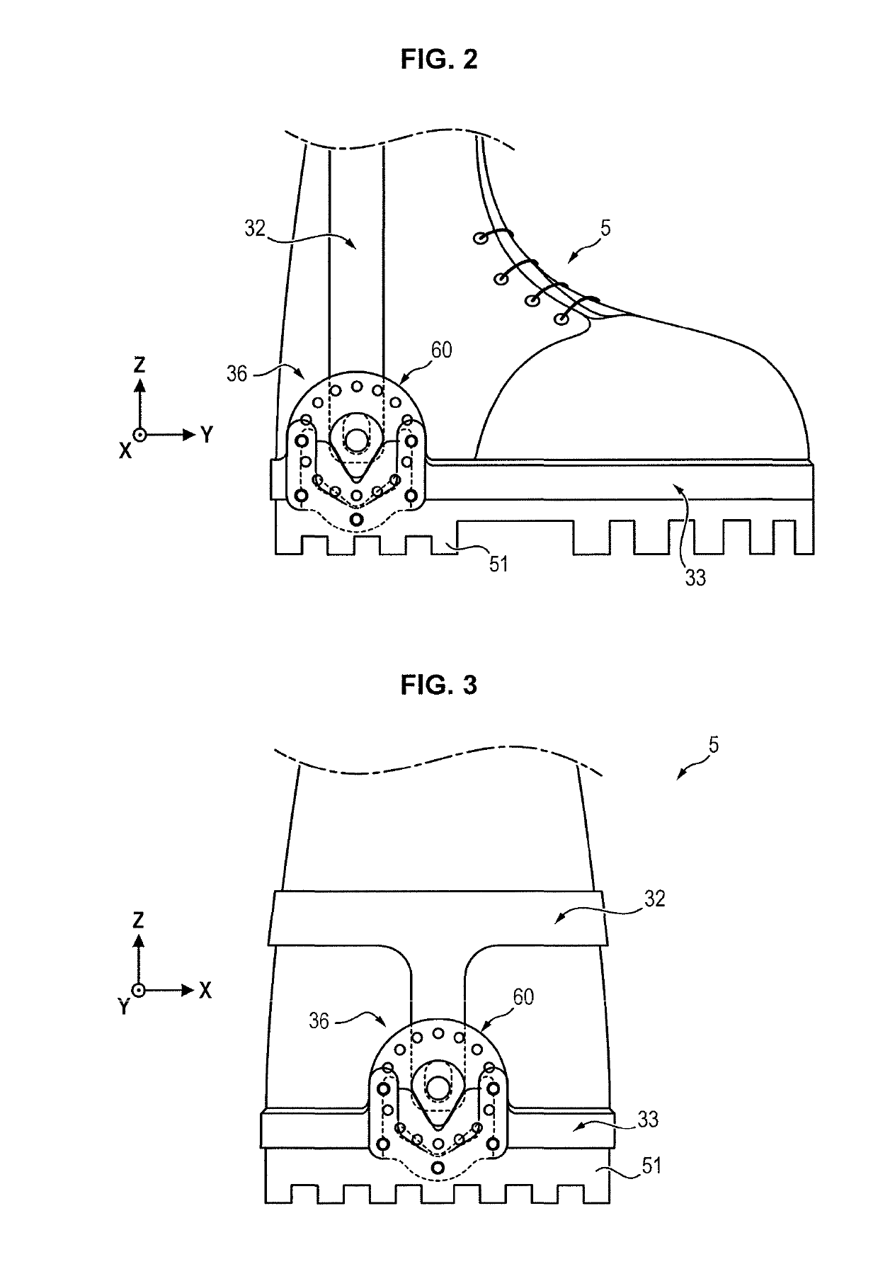
[0066]FIG. 2 shows in more detail an ankle joint 36 conforming to the invention.

[0067]In this first embodiment, the ankle joint 36 is designed to allow a flexural / extensional movement of the foot with respect to the leg of the user.

[0068]In other words, the ankle joint 36 allows a rotation of the shin part 32 with respect to the foot part 33 around an axis of rotation X, parallel to a flexural / extensional axis of the ankle, when the shin part 32 is attached to the leg and the foot part 33 is attached to the foot of the user.

second embodiment

[0069]FIG. 3 shows in more detail an ankle joint 36 conforming to the invention.

[0070]In this second embodiment, the ankle joint 36 is designed to allow an eversion / inversion movement of the foot of the user with respect to the leg.

[0071]In other words, the ankle joint 36 allows rotation of the shin part 32 with respect to the foot part 33 around an axis of rotation Y, parallel to an eversion / inversion axis of the ankle when the tibial part 32 is attached to the leg and the foot part 33 is attached to the foot of the user.

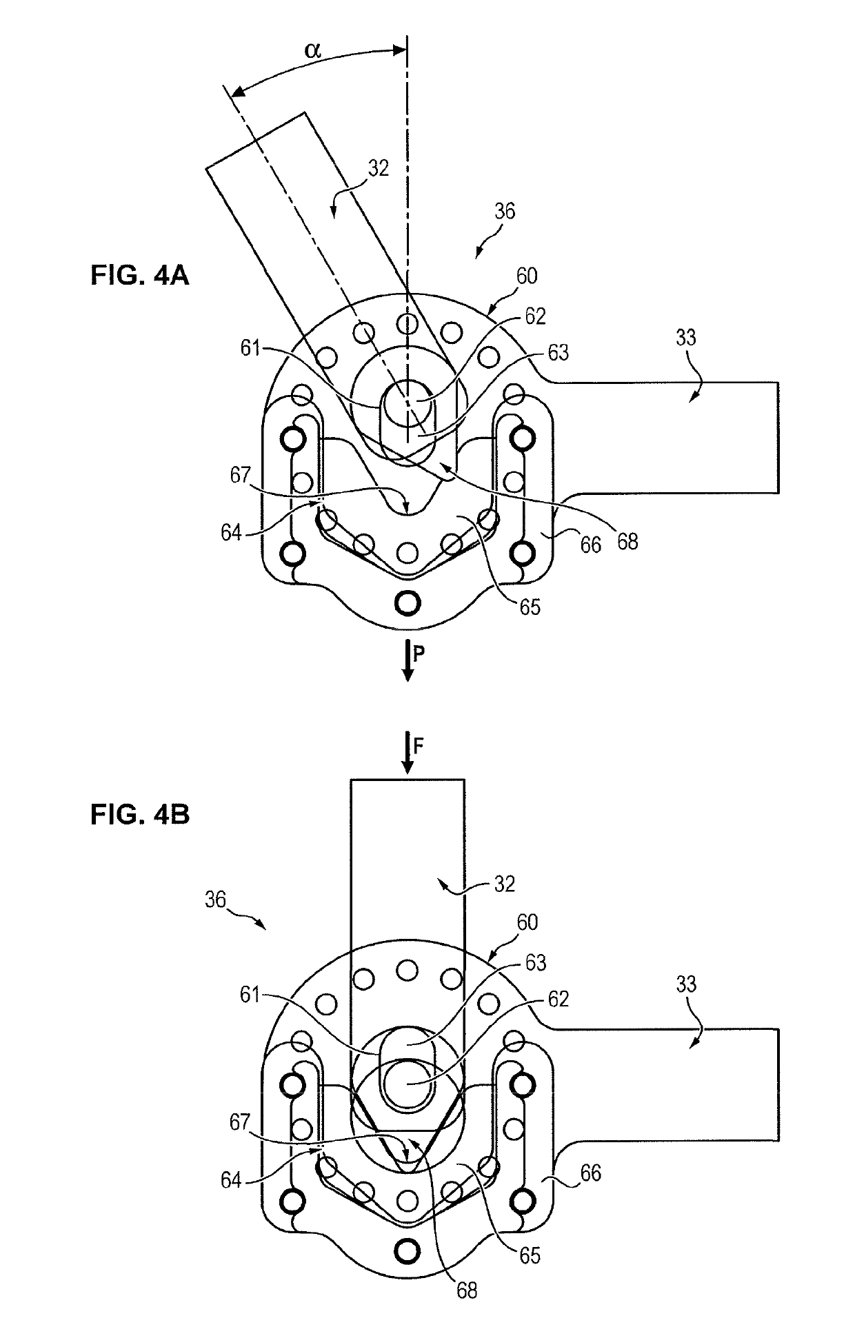
[0072]FIGS. 4A and 4B illustrate in more detail the first ankle joint 36 conforming to a first exemplary embodiment. It should be noted that the second ankle joint 46 is identical to the first ankle joint 36.

[0073]The ankle joint 36 comprises a connecting assembly 60 connecting the shin part 32 to a foot part 33.

[0074]The connecting assembly 60 comprises a guide 61 fixedly mounted with respect to the shin part 32, and a pin 62 fixedly mounted with respect to the fo...


PUM


Abstract

The invention concerns an exoskeleton subassembly comprising: —a first exoskeleton part (32), —a second exoskeleton part (33), —a connecting assembly (60) connecting the first exoskeleton part (32) to the second exoskeleton part (33), the connecting assembly (60) comprising a guide (61) mounted securely relative to one of the first part (32) and the second part (33), and a pin (62) mounted securely relative to the other of the first part (32) and the second part (33), the pin (62) being mounted slidingly inside the guide (61) between a first end position and a second end position, wherein the connecting assembly (60) further comprises a limiting device (64) arranged to allow the pin (62) to rotate relative to the guide (61) when the pin (62) is in the first end position, and to limit the rotation of the pin (62) relative to the guide (61) when the pin (62) is in the second end position, the limiting device (64) comprising a resilient element (65) with which the first exoskeleton part (32) engages when the pin (62) is in the second end position, the resilient element (65) applying an elastic return force on the first exoskeleton part (33) that tends to resist the rotation of the first exoskeleton part (33) and the second exoskeleton part (32) relative to each other.

Description

FIELD OF THE INVENTION[0001]The invention relates to a subassembly of an exoskeleton for providing force assistance to a user.PRIOR ART[0002]Exoskeletons for providing force assistance to the user are mechanical structures positioned in parallel with the human skeleton and which allow an improvement in the physical capacities of the human body.[0003]There exist different types of exoskeletons, of which the shape and the structure depend on the tasks to be accomplished by the user. The two main types of exoskeletons are those designed for assisting the movements of the user on the one hand, and those designed for amplifying the strength capacities of the user on the other hand.[0004]In the case of exoskeletons designed for assisting the movements of the user, the user must generally transport the structure of the exoskeleton because it is disposed on his body, which has the consequence of limiting the freedom of movement of the user and of generating an additional load and associated...

Claims


Application Information

Patent Timeline
IPC IPC(8): A61H3/00A61H1/02
CPCA61H2201/165A61H1/024A61H1/0262A61H1/0244A61H3/008A61H3/00A61H2201/1481A61H2201/164A61H2201/1671A61H2201/1676A61H2205/10A61H2205/12A61H2201/1657A61F5/0125A61F2005/0155A61F2005/0165A61F2005/0179
Inventor SOUCY, FRANCISCOBILODEAU, KATIAZOSO, NATHANIELBAPTISTA, JONATHANGRENIER, JORDANE
Owner SAFRAN ELECTRONICS & DEFENSE
Why Eureka
Try Eureka