
Adjustable cladding for mitigating wind-induced vibration of high-rise structures

a technology of adjustable cladding and high-rise structures, which is applied in the direction of shock-proofing, flooring, covering/linings, etc., can solve the problems of reducing the amount of leasable floor space, and reducing the amount of wind-induced vibration of the structure. , to achieve the effect of reducing the wind-induced vibration of the structure, and reducing the wind-induced vibration

Active Publication Date: 2019-11-14
THORNTON TOMASETTI INC
View PDF0 Cites 3 Cited by
  • Summary
  • Abstract
  • Description
  • Claims
  • Application Information

AI Technical Summary

Benefits of technology

This patent is about a system that reduces wind-induced vibration on buildings. It consists of a cladding that has movable panels that can be controlled by a processor to move based on the wind speed and direction parameters. By doing so, the system can reduce wind-induced vibration on the building and make it more stable. This technology can be applied to both new construction and existing buildings.

Problems solved by technology

However, each of the general implementations currently known in the art is subject to limitations inherent to the structure and physical principles underlying these devices.
For example, devices based upon a solid mass counterweight, such as tuned mass dampers (“TMDs”) and active mass dampers (“AMDs”), are expensive and heavy (e.g., weighing hundreds of tons).
However, a solid weight counter reduces the amount of leasable floor space in a building and typically requires extensive customization thereby increasing costs.
As with the solid mass dampers, traditional TLDs suffer from increased costs resulting from the custom-built nature of these devices and maintenance costs associated with maintaining a large tank of liquid and again the concomitant loss in leasable floor space.
A limitation of the TLCD is that it is tuned to a particular frequency by design and cannot be tuned to a different frequency without a major retrofit of the finished damper.
Furthermore, TLCDs typically require a large amount of horizontal space and so they cannot fit in buildings with small or narrow footprints, such as slim skyscrapers, which are becoming increasingly popular among urban developers.
Finally, the TLCD tank is typically made of concrete and may leak over time thereby increasing costs.
However, the spring TLCD remains subject to a substantial limitation in that the adjustable stiffness of the gas spring can only add to the gravity-induced stiffness of the U-shaped pipe.
As a result, the spring TLCD cannot be relied upon to efficiently dampen wind-induced vibrations in tall buildings (e.g., slender skyscrapers) above a height-to-width ratio of 10.
Furthermore, the vertical ends required by a TLCD are obtrusive and reduce the number of viable placement locations within a structure.

Method used


Image

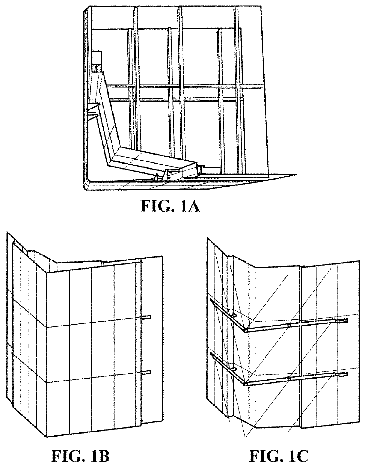
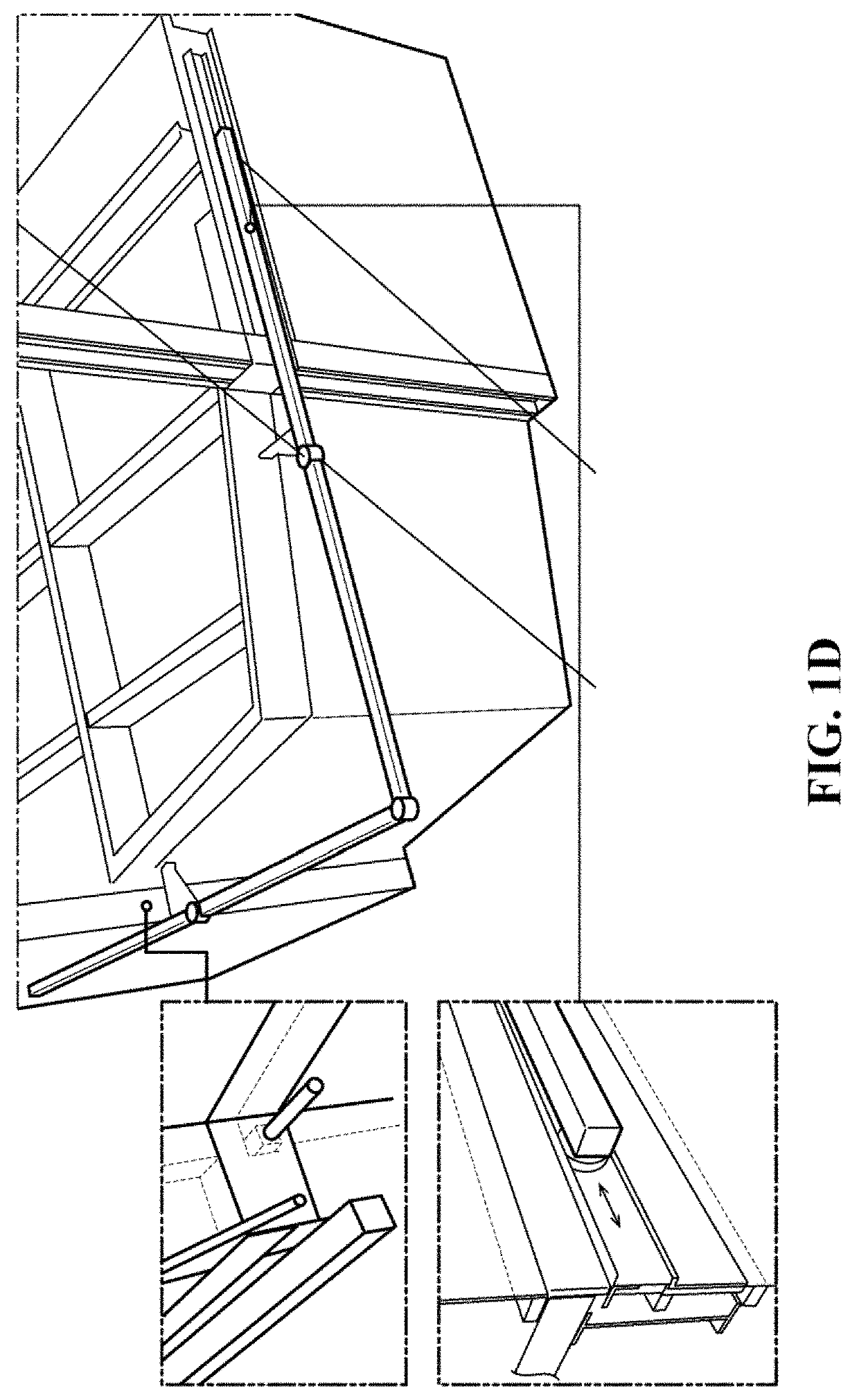
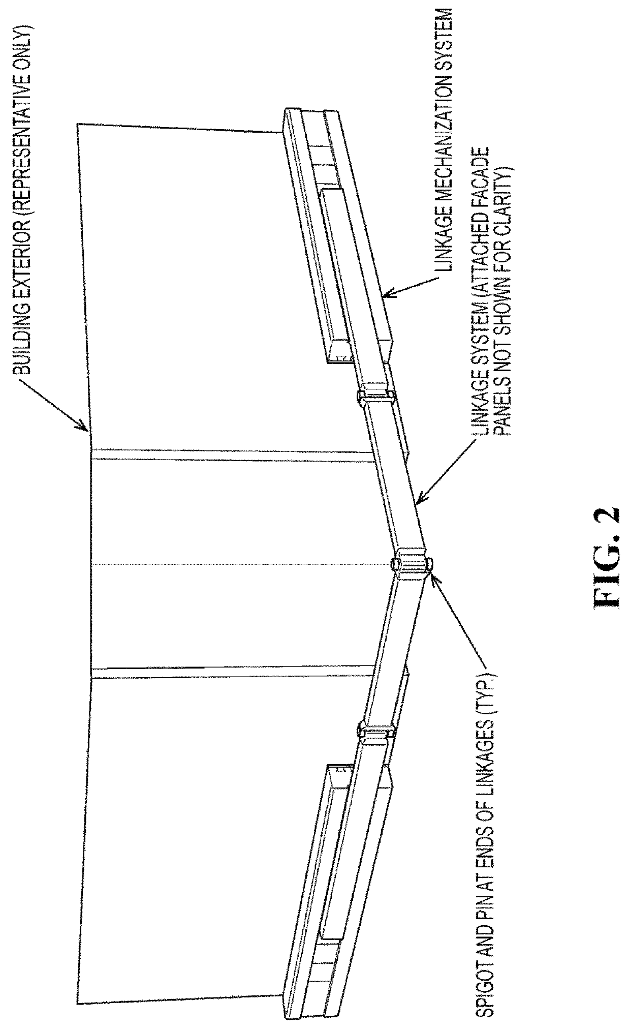
  • Adjustable cladding for mitigating wind-induced vibration of high-rise structures
  • Adjustable cladding for mitigating wind-induced vibration of high-rise structures
  • Adjustable cladding for mitigating wind-induced vibration of high-rise structures

Examples


Embodiment Construction

[0035]Exemplary aspects of the disclosure are described herein in the context of an adjustable cladding system and related methods, various aspects of which being suitable to reduce vibrations when incorporated into tall buildings or structures such as skyscrapers and towers. Persons of ordinary skill in the art will realize that the following description is illustrative only and is not intended to be in any way limiting. Other aspects will readily suggest themselves to those skilled in the art having the benefit of this disclosure. Reference will now be made in detail to implementations of the example aspects as illustrated in the accompanying drawings. The same reference indicators will be used to the extent possible throughout the drawings and the following description to refer to the same or like items.

[0036]As indicated above, many modern structures (e.g., tall and super tall building) are adversely affected by vortex-induced vibration. Traditionally, wind-induced motion contro...


PUM


Abstract

A system, device and method for reducing wind-induced vibration using cladding includes one or more movable panels attached to an outer façade of a high-rise building, skyscraper or any other structure subject to wind-induced vibration.

Description

CROSS-REFERENCE TO RELATED APPLICATION[0001]The application claims priority to U.S. Provisional Patent Application No. 62 / 669,528, filed on May 10, 2018, the contents of which are hereby incorporated in their entirety.TECHNICAL FIELD[0002]The present disclosure is directed to systems, devices and methods for reducing vibration, and in some aspects provides systems for reducing wind-induced vibration using cladding comprising one or more movable panels attached to an outer façade of a high-rise building, skyscraper or any other structure subject to wind-induced vibration.BACKGROUND[0003]Tall buildings often require supplemental damping to keep the wind-induced vibrations at a level imperceptible by most building occupants during wind storms. Damping devices have been developed which are able to mitigate structural vibration to varying extents. However, each of the general implementations currently known in the art is subject to limitations inherent to the structure and physical princ...

Claims


Application Information

Patent Timeline
IPC IPC(8): E04H9/14E04B1/98
CPCE04B1/985E04H9/14E04F2290/04E04F13/0733E04F13/12E04F13/145E04F13/081E04H9/0215
Inventor BLASETTI, ANDREW
Owner THORNTON TOMASETTI INC
Learn More