This helps you quickly interpret patents by identifying the three key elements:
Problems solved by technology
Method used
Benefits of technology
Benefits of technology
The patent is about a new cartridge and image forming apparatus that has a charging roller to improve image quality while preventing soiling.
Problems solved by technology
However, as a result of intensive studies by the inventors, it was found that in the case where a surface roughness of a certain degree or more is imparted to the charging roller, the amount of electrical discharge becomes uneven due to recesses and projections on the surface of the charging roller, and as a result small unevenness of density occurs in the output image.
This unevenness of density degrades the uniformity of a halftone region, and gives a rough texture to the output image.
In particular, in the case where a direct current charging system: DC charging system is employed to simplify the apparatus, the problem of the unevenness of density is more critical.
Improving the charging uniformity by performing pre-exposure of the photosensitive member to suppress the unevenness of density after transfer and before charging can be also considered, but this leads to increase in the cost.
Method used
Image
Click on the blue label to locate the original text in one second.
Reading with bidirectional positioning of images and text.
Examples
first exemplary embodiment
Image Forming Apparatus
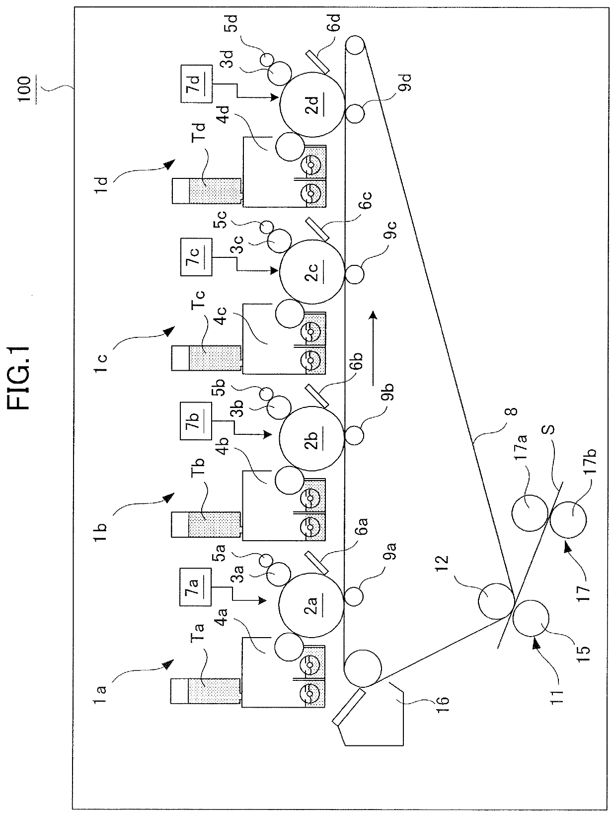
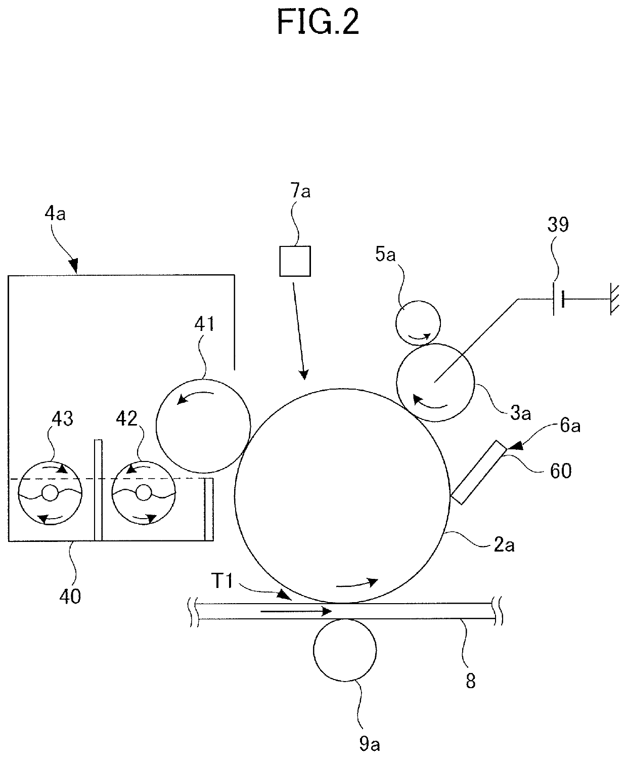
[0025]FIG. 1 is a configuration diagram of an image forming apparatus 100 of a 4-drum in-line system. The image forming apparatus 100 includes four image forming units 1a, 1b, 1c, and 1d that respectively form images of yellow, magenta, cyan, and black. The four image forming units 1a, 1b, 1c, and 1d are arranged in a line with equal intervals therebetween.
[0026]The image forming units 1a to 1d respectively include photosensitive drums 2a, 2b, 2c, and 2d serving as image bearing members. The photosensitive drums 2a to 2d each have a photosensitive layer of an organic photoconductor: OPC having a negative charging polarity on a base drum body of aluminum or the like, and are each rotationally driven by a driving unit at a predetermined process speed.
[0027]Charging rollers 3a, 3b, 3c, and 3d, charging cleaning members 5a, 5b, 5c, and 5d, developing units 4a, 4b, 4c, and 4d, and drum cleaning units 6a, 6b, 6c, and 6d are respectively disposed around the photosens...
second exemplary embodiment
[0092]Next, a charging roller according to a second exemplary embodiment will be described. In the present exemplary embodiment, similarly to the first exemplary embodiment, an image defect in which the image density becomes low in a partial region of the output image is suppressed by setting the root mean square slope RΔq related to the roughness profile of the surface of the charging roller to be equal to or smaller than a predetermined value. This image defect will be referred to as a ghost image.
Mechanism of Occurrence of Ghost Image
[0093]The mechanism of occurrence of a ghost image will be described with reference to FIG. 7. There is a tendency that a ghost image is likely to occur in an image forming unit on the downstream side in an image forming apparatus of an in-line system, that is, in an image forming apparatus of a tandem type. Therefore, FIG. 7 illustrates an enlarged view of the black image forming unit 1d of FIG. 1. In addition, in the following description, elements...
PUM
Abstract
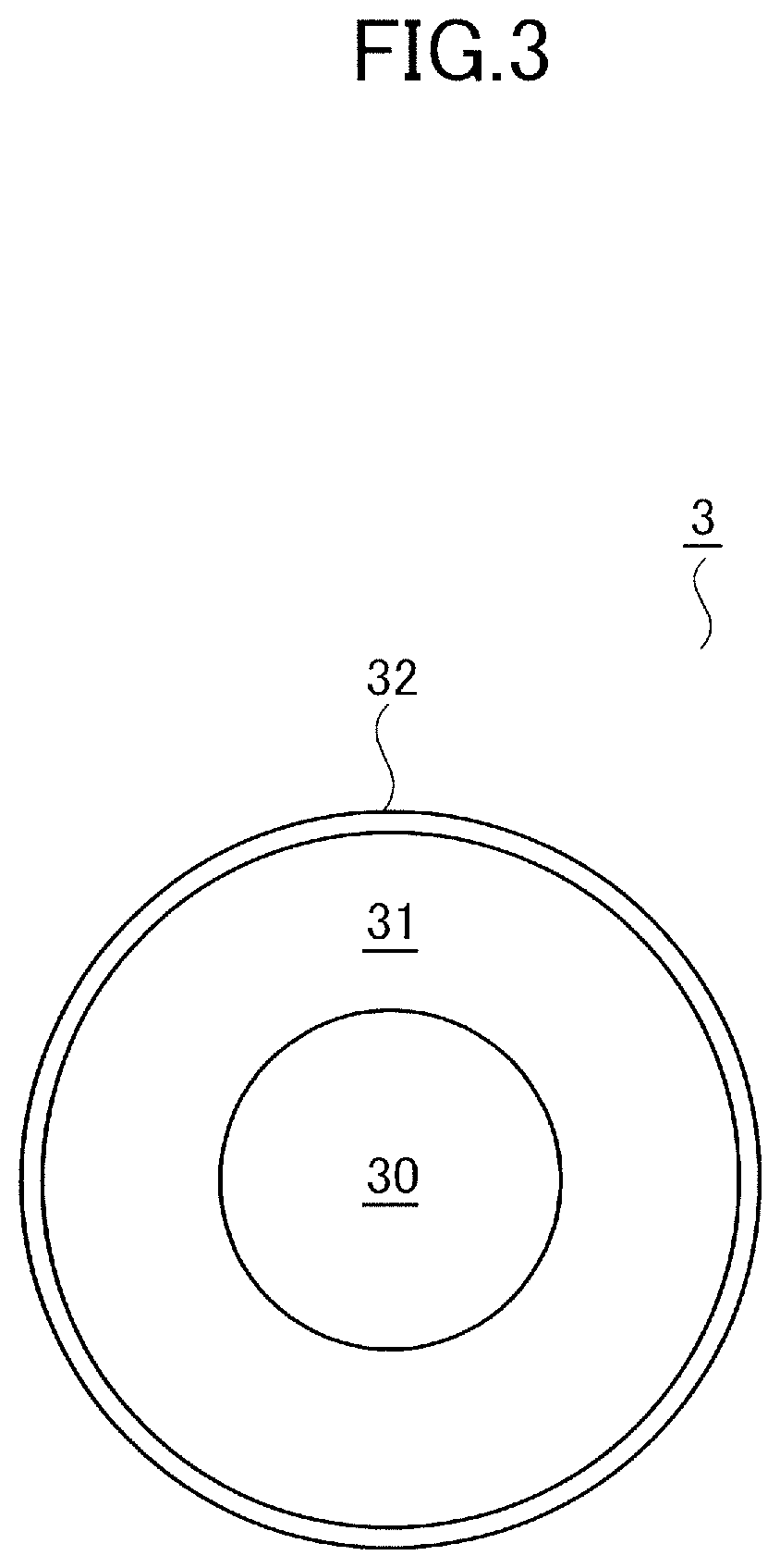
An image forming apparatus includes a photosensitive member and a charging roller to which a direct currentvoltage is applied. A difference between a first potential (before charging) and a second potential (after charging) of a surface of the photosensitive member in an image forming operation is smaller than 100 V. The charging roller includes a shaft portion, an elastic layer provided on an outer periphery of the shaft portion, and a surface layer provided on an outer periphery of the elastic layer. A ten point height of roughness profile Rz (μm) and a root mean square slope RΔq with respected to a surface of the charging roller satisfy Rz≥7 and RΔq≤0.1.
Description
BACKGROUND OF THE INVENTIONField of the Invention[0001]The present invention relates to a cartridge and an image forming apparatus including a charging roller configured to charge an image bearing member in an electrophotographic process.Description of the Related Art[0002]For a charging unit configured to charge an image bearing member in an image forming apparatus of an electrophotographic system, a contact charging system in which a voltage is applied to a charging roller brought into contact with the image bearing member is widely used. There is a case where a so-called filming phenomenon occurs in which soiling matter such as toner attached to the image bearing member, an external additive added to the toner, and an electrical discharge product generated at the time of charging is attached to and accumulated on such a charging roller. When a filming phenomenon occurs, sometimes an image defect occurs in a position corresponding to a part of the charging roller to which the soil...
Claims
Application Information
Patent Timeline
Application Date:The date an application was filed.
Publication Date:The date a patent or application was officially published.
First Publication Date:The earliest publication date of a patent with the same application number.
Issue Date:Publication date of the patent grant document.
PCT Entry Date:The Entry date of PCT National Phase.
Estimated Expiry Date:The statutory expiry date of a patent right according to the Patent Law, and it is the longest term of protection that the patent right can achieve without the termination of the patent right due to other reasons(Term extension factor has been taken into account ).
Invalid Date:Actual expiry date is based on effective date or publication date of legal transaction data of invalid patent.

