Multi-display stand

a multi-display, stand technology, applied in the direction of stand/trestle, machine support, mechanical apparatus, etc., can solve the problem that the use of such operating system with one display is less convenien

Active Publication Date: 2019-11-21
HUANG MING HSIEN
View PDF8 Cites 6 Cited by
  • Summary
  • Abstract
  • Description
  • Claims
  • Application Information

AI Technical Summary

Benefits of technology

[0008]The invention provides a multi-display stand, in which the angles at which the user rotates the supporting arms can be effectively limited to prevent the multi-display stand from being out of balance and toppling over.
[0025]Based on the above, in the multi-display stand according to the embodiments of the invention, each of the supporting arms is radially rotatable about the central axis with respect to the standing rod between the first position and the second position. When the supporting arm is at the first position, the tenon abuts against the first position-limiting wall. When the supporting arm is at the second position, the tenon abuts against the second position-limiting wall. Accordingly, the angles at which the user rotates the supporting arms can be effectively limited to prevent the multi-display stand from being out of balance and toppling over.

Problems solved by technology

A stand which normally allows only one display to be mounted is less convenient when used with such operating system.
Besides, when the user moves his / her seat and intends to adjust the displays to face him / her directly, the user needs to move one of the displays as well as the stand, move the other display as well as the stand, and then make adjustment to set the desired included angle, which causes inconvenience and is laborious.

Method used


Image

  • Multi-display stand
  • Multi-display stand
  • Multi-display stand

Examples


Embodiment Construction

[0040]Reference will now be made in detail to the present preferred embodiments of the invention, examples of which are illustrated in the accompanying drawings. Wherever possible, the same reference numbers are used in the drawings and the description to refer to the same or like parts.

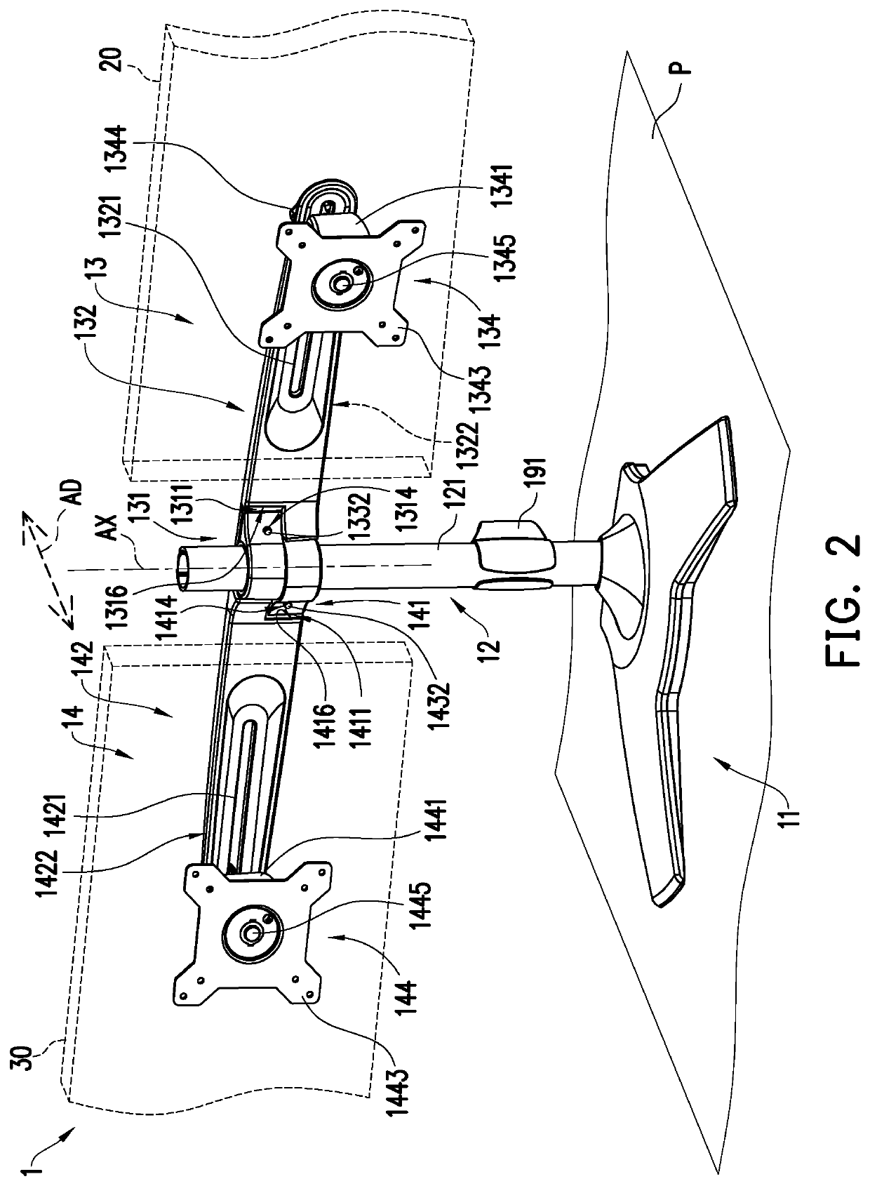
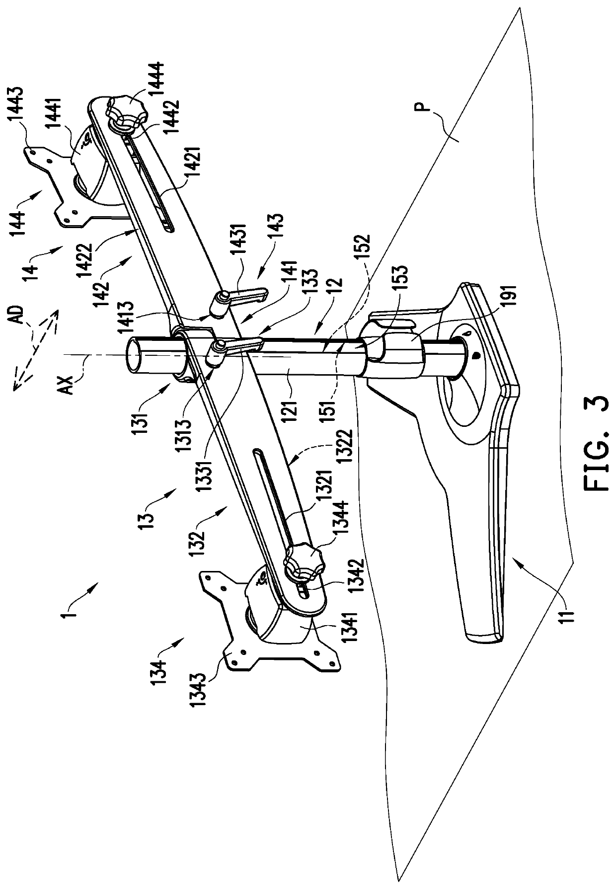
[0041]FIG. 2 is a schematic perspective view of a multi-display stand to which a first display and a second display are assembled according to an embodiment of the invention. FIG. 3 is a schematic perspective view of the multi-display stand of FIG. 2 from another perspective. FIG. 4 is a schematic exploded view of the multi-display stand of FIG. 2. For the ease and clarity of illustration, a display 20 and a display 30 are schematically shown in dotted lines in FIG. 2, and some components that are shielded are shown in dotted lines in FIG. 4.

[0042]Referring to FIGS. 2, 3, and 4, a multi-display stand 1 of the embodiment includes a base 11, a standing rod 12, a first supporting arm 13, a second suppor...


PUM


Abstract

A multi-display stand configured to support a plurality of displays is provided. The multi-display stand includes a standing rod, a plurality of supporting arms, and a position-limiting member. The standing rod extends along a central axis. The supporting arms are disposed on the standing rod. Each of the supporting arms supports one of the displays. The position-limiting member is disposed between the standing rod and each of the supporting arms and includes at least one first position-limiting wall, at least one second position-limiting wall, and at least one tenon. Each of the supporting arms is radially rotatable about the central axis with respect to the standing rod between a first position and a second position. When the supporting arm is at the first position, the tenon abuts against the first position-limiting wall. When the supporting arm is at the second position, the tenon abuts against the second position-limiting wall.

Description

CROSS-REFERENCE TO RELATED APPLICATION[0001]This application claims the priority benefit of U.S. provisional application Ser. No. 62 / 673,133, filed on May 18, 2018. The entirety of the above-mentioned patent application is hereby incorporated by reference herein and made a part of this specification.BACKGROUND OF THE INVENTION1. Field of the Invention[0002]The invention relates to a multi-display stand, and particularly relates to a multi-display stand for supporting a plurality of displays.2. Description of Related Art[0003]Owing to the development of software in recent years, operating systems compatible with use of multiple displays at the same time keep emerging and become more and more popular. A stand which normally allows only one display to be mounted is less convenient when used with such operating system. For example, to adjust the included angle between displays, it is very likely that at least one of the displays, together with the stand, needs to be lifted up and then p...

Claims


Application Information

Patent Timeline
Patent Type & Authority Applications(United States)
IPC IPC(8): F16M11/08F16M11/20F16M11/16
CPCF16M2200/08F16M2200/02F16M11/2085F16M11/08F16M11/16F16M11/045F16M11/2014F16M11/24F16M2200/027F16M11/04
Inventor HUANG, MING-HSIEN
Owner HUANG MING HSIEN
Why Eureka
Try Eureka