
3D monitoring server using 3D BIM object model and 3D monitoring system comprising it

a monitoring server and object model technology, applied in the field of three-dimensional monitoring systems, can solve the problems of extremely rare user interface examples, research and development on the basis of 3d monitoring systems

Inactive Publication Date: 2019-12-05
UNIV OF SEOUL IND COOP FOUND
View PDF0 Cites 21 Cited by
  • Summary
  • Abstract
  • Description
  • Claims
  • Application Information

AI Technical Summary

Benefits of technology

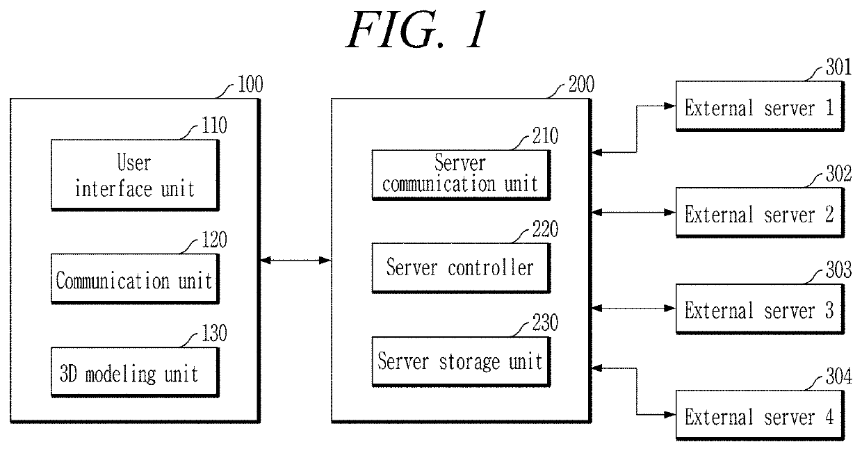
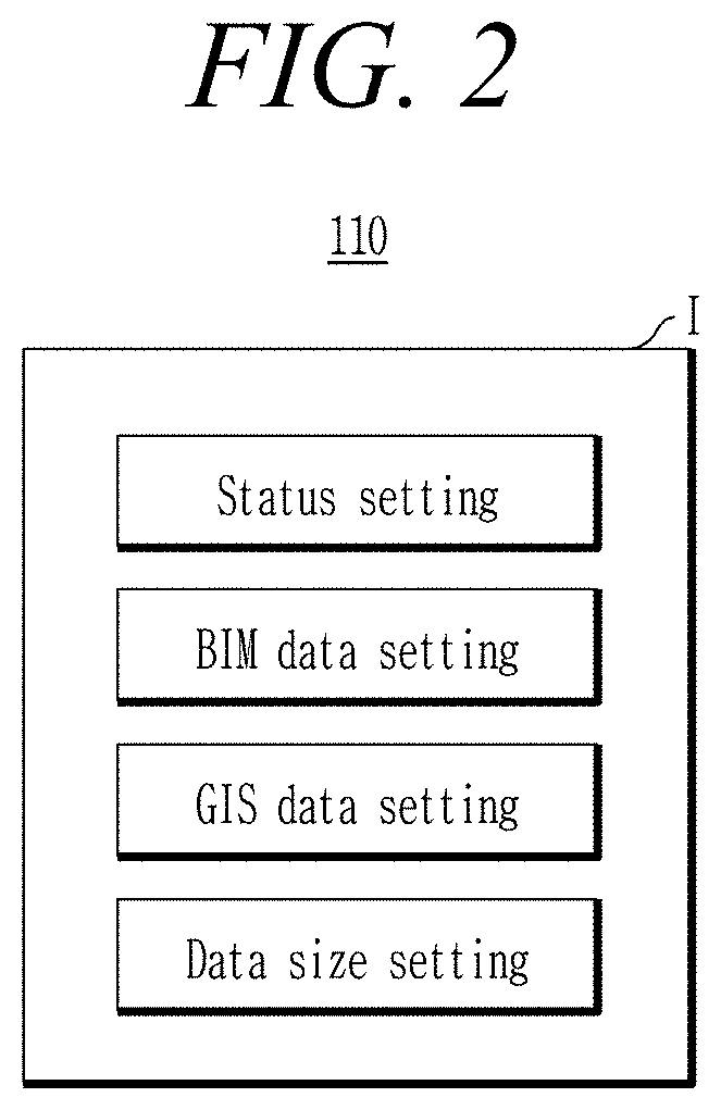
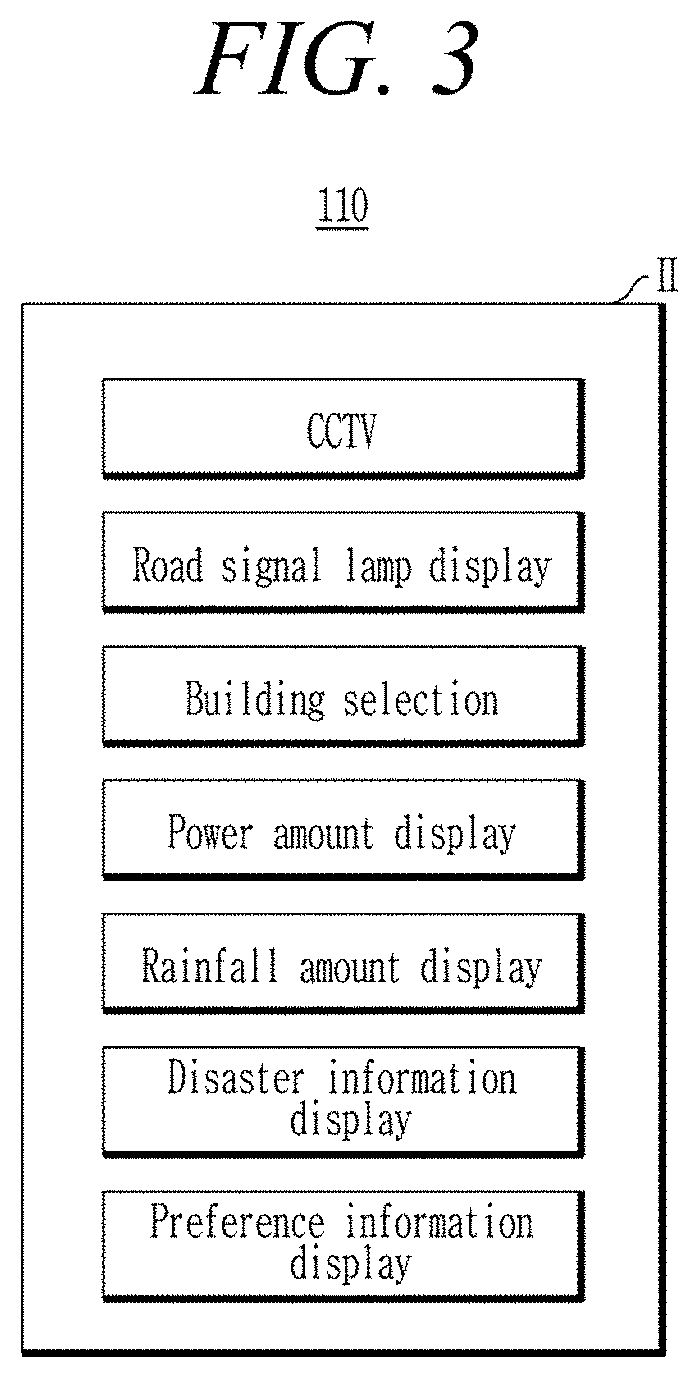
The present invention provides a 3D monitoring server and system using BIM and GIS data to model and monitor structures and their surrounding environment. The server controller includes a 3D modeling module for creating 3D models, a monitoring information mapping module for integrating monitoring information with the BIM and GIS data, and an alarm generation module for generating alarms based on the monitoring information. The user terminal includes a user interface for setting user preferences and receiving BIM and GIS data, and a 3D modeling unit for creating specific buildings, roads, and objects in specific colors. The system allows for real-time monitoring and modeling of structures and their surroundings, providing valuable information for safety and security purposes.

Problems solved by technology

Such a Smart City is being currently used in about 30 domestic cities of Korea, but there is no example that implements a user interface, especially 3D modeled user interface, and the Smart City of the number of hundreds in the world is being developed, but an example of a user interface considering the user is extremely rare.
Furthermore, there is required development of a 3D monitoring system that may easily monitor a specific building and peripheral status information of the specific building through a user terminal instead of directly exploring a peripheral status, but there is no research and development on the 3D monitoring system.

Method used


Image

  • 3D monitoring server using 3D BIM object model and 3D monitoring system comprising it
  • 3D monitoring server using 3D BIM object model and 3D monitoring system comprising it
  • 3D monitoring server using 3D BIM object model and 3D monitoring system comprising it

Examples


Embodiment Construction

[0032]The present inventive concept may be variously changed and have several embodiments, and is intended to illustrate specific embodiments and describe in detail specific embodiments in a detailed description. It is to be understood, however, that the present inventive concept is not to be limited to the specific embodiments, but includes all modifications, equivalents, and alternatives falling within the spirit and scope of the invention.

[0033]Terms used in the present disclosure are used for describing a specific embodiment and do not limit the present invention. Unless the context otherwise clearly indicates, words used in the singular include the plural, the plural includes the singular. Further, in the present inventive concept, a term “comprise” or “have” indicates presence of a characteristic, numeral, step, operation, element, component, or combination thereof described in a specification and does not exclude presence or addition of at least one other characteristic, nume...


PUM


Abstract

Disclosed are a three-dimensional (3D) monitoring server using a 3D BIM object model and a 3D monitoring system including the same capable of implementing 3D modeling using BIM information and GIS information and monitoring buildings and peripheral status information of the buildings using 3D modeling. The 3D monitoring server includes a server communication unit for performing a function of interworking with a user terminal through a wired and wireless communication network; a server storage unit for storing GIS data for integrating BIM data for virtually modeling a building, geographical data occupying a spatial position, and attribute data related to the geographical data; and a server controller for controlling to map monitoring information on the building or a peripheral status of a predetermined range including the building received from an external server to the BIM data and the GIS data to transmit the monitoring information to the user terminal.

Description

CROSS-REFERENCE TO RELATED APPLICATION[0001]This application claims priority to Korean Patent Application No. 10-2018-0065021, filed on Jun. 5, 2018, the disclosure of which is incorporated herein by reference in its entirety.BACKGROUNDTechnical Field[0002]The present disclosure relates to a three-dimensional monitoring system, and more particularly, to a three-dimensional monitoring server using a three-dimensional BIM object model and a three-dimensional monitoring system including the same capable of implementing three-dimensional (3D) modeling using building information modeling (BIM) information and geographic information system (GIS) information and monitoring buildings and peripheral status information of the buildings using 3D modeling.Description of the Related Art[0003]In recent years, interest in so-called Smart City for forming public functions of major cities in a network using advanced information communication technology (ICT) is growing. The Smart City refers to a fu...

Claims


Application Information

Patent Timeline
Patent Type & Authority Applications(United States)
IPC IPC(8): G06T17/05G08B21/18
CPCG06T17/05G08B21/18G06T2200/24G06T19/20G06T2219/2012G08B21/10G08B31/00G06Q50/10
Inventor KIM, HYUNJOO
Owner UNIV OF SEOUL IND COOP FOUND
Learn More