Sphygmomanometer, blood pressure measurement method, and device

a blood pressure measurement and manometer technology, applied in the field of sphygmomanometers, can solve the problem of large measurement error of blood pressure values, and achieve the effect of accurately measuring blood pressur

Active Publication Date: 2019-12-12
ORMON CORP +1
View PDF0 Cites 1 Cited by
  • Summary
  • Abstract
  • Description
  • Claims
  • Application Information

AI Technical Summary

Benefits of technology

The present invention aims to provide a sphygmomanometer, a blood-pressure measurement method, and a device that can accurately measure blood pressure on the wrist using a bag-shaped blood-pressure measurement cuff. The technical effect is to improve the accuracy of blood pressure measurement on the wrist.

Problems solved by technology

The technical problem addressed in this patent document relates to improving the comfort level when wearing a conventional sphygmomanometer during blood pressure measurements.

Method used


Image

  • Sphygmomanometer, blood pressure measurement method, and device
  • Sphygmomanometer, blood pressure measurement method, and device
  • Sphygmomanometer, blood pressure measurement method, and device

Examples


Embodiment Construction

[0039]Embodiments of the present invention will now be described in detail with reference to the drawings.

(Configuration of Sphygmomanometer)

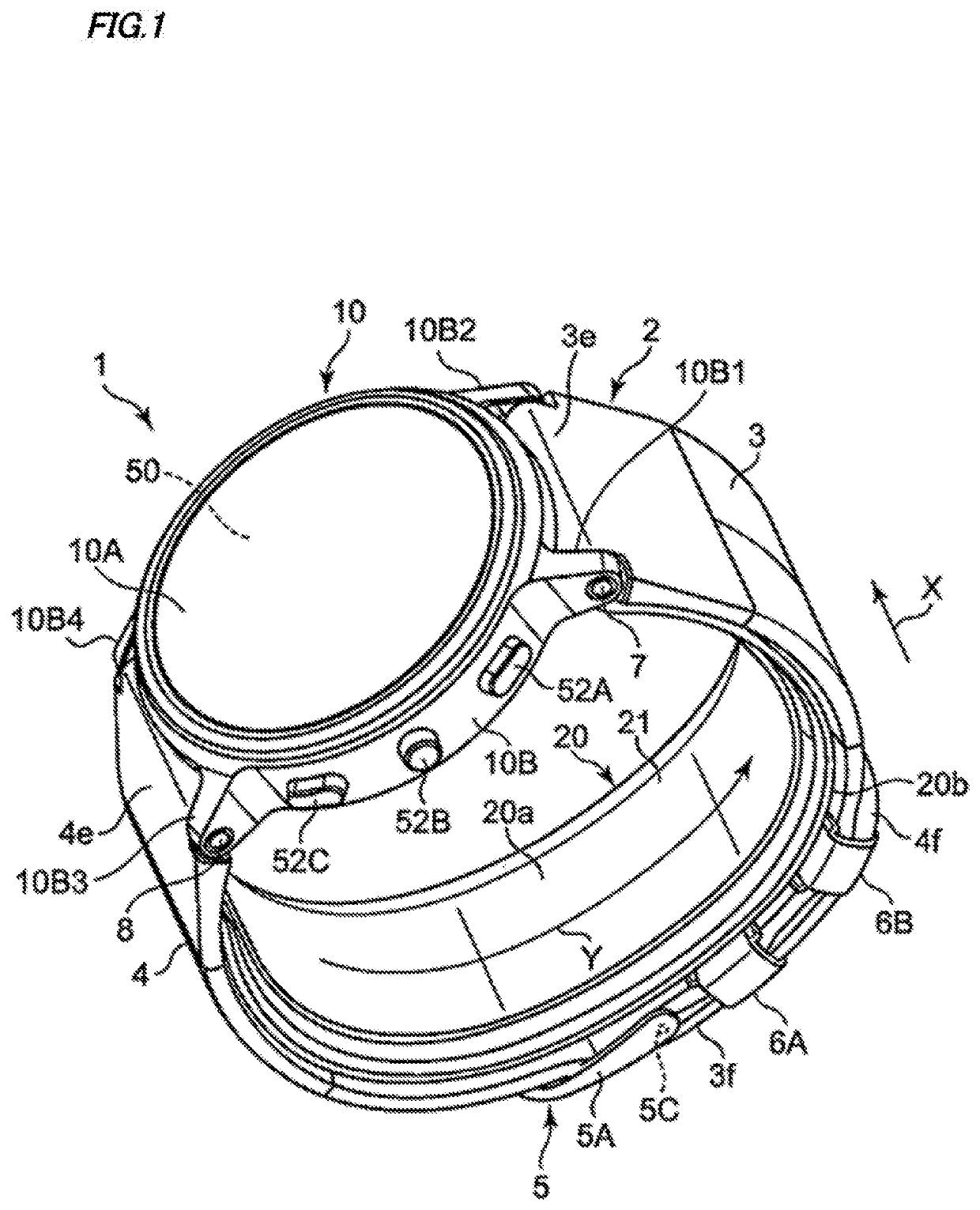
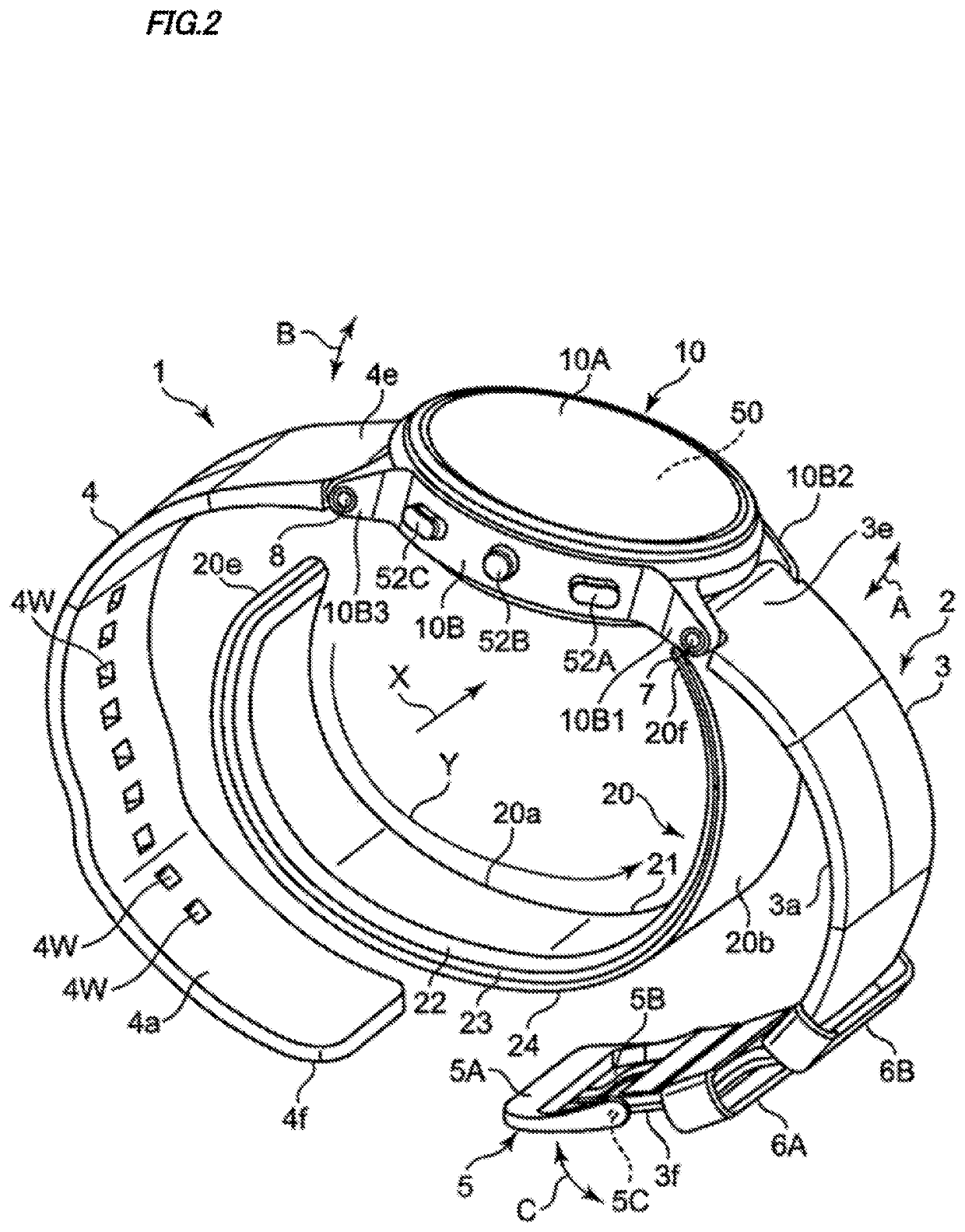
[0040]FIG. 1 shows an appearance of a sphygmomanometer (generally denoted by reference numeral 1) of an embodiment of the present invention with a belt 2 fastened as viewed obliquely. FIG. 2 shows the appearance of the sphygmomanometer 1 with the belt 2 released as viewed obliquely.

[0041]As shown in these figures, the sphygmomanometer 1 roughly includes a main body 10, the belt 2 extended from the main body 10 and to be worn to wrap a measurement site (in this example, as shown in FIG. 13C described later, a left wrist 90 is supposed to be the measurement site), and a strap-shaped cuff structure 20 having one end 20f attached to the main body 10. The dimension in a width direction X of the belt 2 is set to 29 mm in this example. The thickness of the belt 2 is set to 2 mm in this example.

[0042]In this example, the main body 10 has a substantiall...


PUM


Abstract

A sphygmomanometer includes: a sensing cuff that includes a second sheet disposed to face the pressing member's inner circumferential surface and a first sheet facing the second sheet; a fluid storage control part providing a control of supplying and storing the pressure-transmitting fluid into sensing cuff in a worn state wherein the pressing member and sensing cuff are worn on the wrist; and a blood-pressure calculating part calculating a blood pressure based on a pressure of the pressure-transmitting fluid stored in the sensing cuff. The fluid storage control part supplies fluid in the worn state such that the first and second sheets are in contact with each other in a region corresponding to an ulna, a region corresponding to a radius, and a region corresponding to a tendon while first and second sheets are separated from each other in regions corresponding to two arteries that are radial and ulnar arteries.

Description


Claims


Application Information

Patent Timeline
Owner ORMON CORP
Why Eureka
Try Eureka