Engine System Having Containment Blanket And Method Of Improving Engine Safety

a technology of containment blanket and engine, which is applied in the direction of engines, machines/engines, mechanical equipment, etc., can solve the problems of high pressure and flow rate of hydraulic fracturing operations, internal components such as rods and crank shafts, being ejected under high force, and people working in the area being killed, so as to improve the safety of an engine

Active Publication Date: 2019-12-12
NEXTIER COMPLETION SOLUTIONS INC
View PDF0 Cites 108 Cited by
  • Summary
  • Abstract
  • Description
  • Claims
  • Application Information

AI Technical Summary

Benefits of technology

[0016]According to another embodiment, a method of improving safety of an engine having an engine housing and moving parts for converting energy into mechanical motion is described. The method includes (1) providing a first containment blanket having a fastening system and a sheet member with upper and lower ends; (2) laterally shrouding the engine housing with the sheet member of the first containment blanket such that the lower end of the sheet member of the first containment blanket extends below a bottom of the engine housing; and (3) using the fastening system of the first containment blanket to hold the sheet member of the first containment blanket in place such that the first containment blanket laterally shrouds the engine housing with the lower end of the sheet member of the first containment blanket extending below the bottom of the engine housing. Debris projected from the engine housing is contained by the sheet member of the first containment blanket and directed downwardly relative to the engine housing.

Problems solved by technology

Hydraulic fracturing operations involve very high pressures and flow rates.
Incidents have occurred where major engine failures resulted in internal components, such as rods and crank shafts, being ejected under high forces.
And incidents have occurred where major engine failures resulted in flammable fluid, such as oils and fuel, being sprayed randomly from one pump system and onto other units—resulting in fires because of hot surfaces (e.g., exhaust manifolds) being present.
People working in the area have been killed when these various failure incidents occurred, and millions of dollars of equipment have been lost.

Method used


Image

  • Engine System Having Containment Blanket And Method Of Improving Engine Safety
  • Engine System Having Containment Blanket And Method Of Improving Engine Safety
  • Engine System Having Containment Blanket And Method Of Improving Engine Safety

Examples


Embodiment Construction

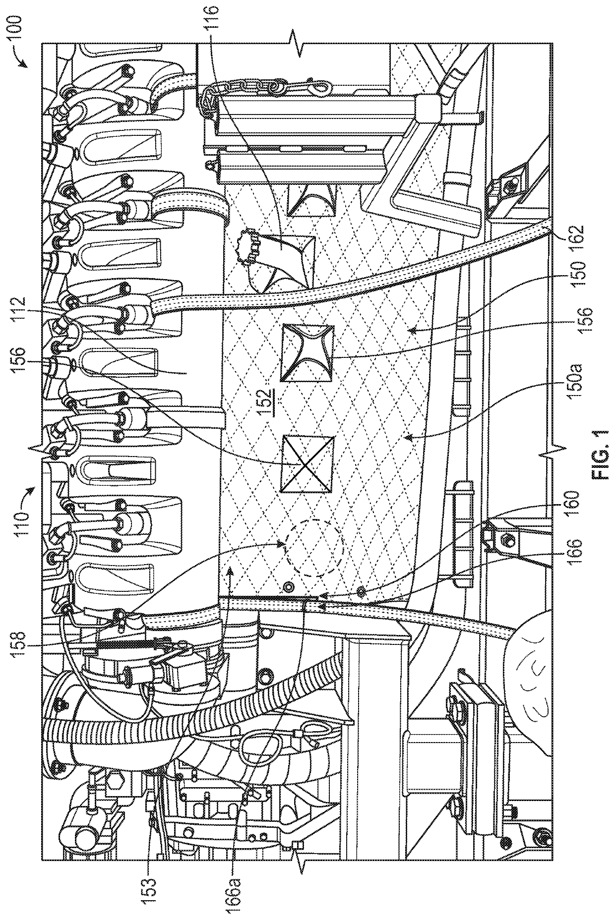
[0022]The failures experienced in high pressure pump units are fundamentally similar even though the units are configured using different sized engines, transmissions, power ends, radiators, et cetera. First, there is an internal failure of one or more major engine components under load, the resulting forces then cause the housing (also referred to as the block or casting) of the main engine structure to fracture, and finally various parts, including fluids (e.g., flammable liquids) and solids, may be ejected. In other words, there is a resultant loss of containment by the block, whereby fluids and / or solids may be allowed to escape with high force. This exposes nearby equipment to further damage, including mechanical damage, chemical damage, and temperature (or “burning”) damage. People in the vicinity of the engine can also be hurt by flying debris or fluids.

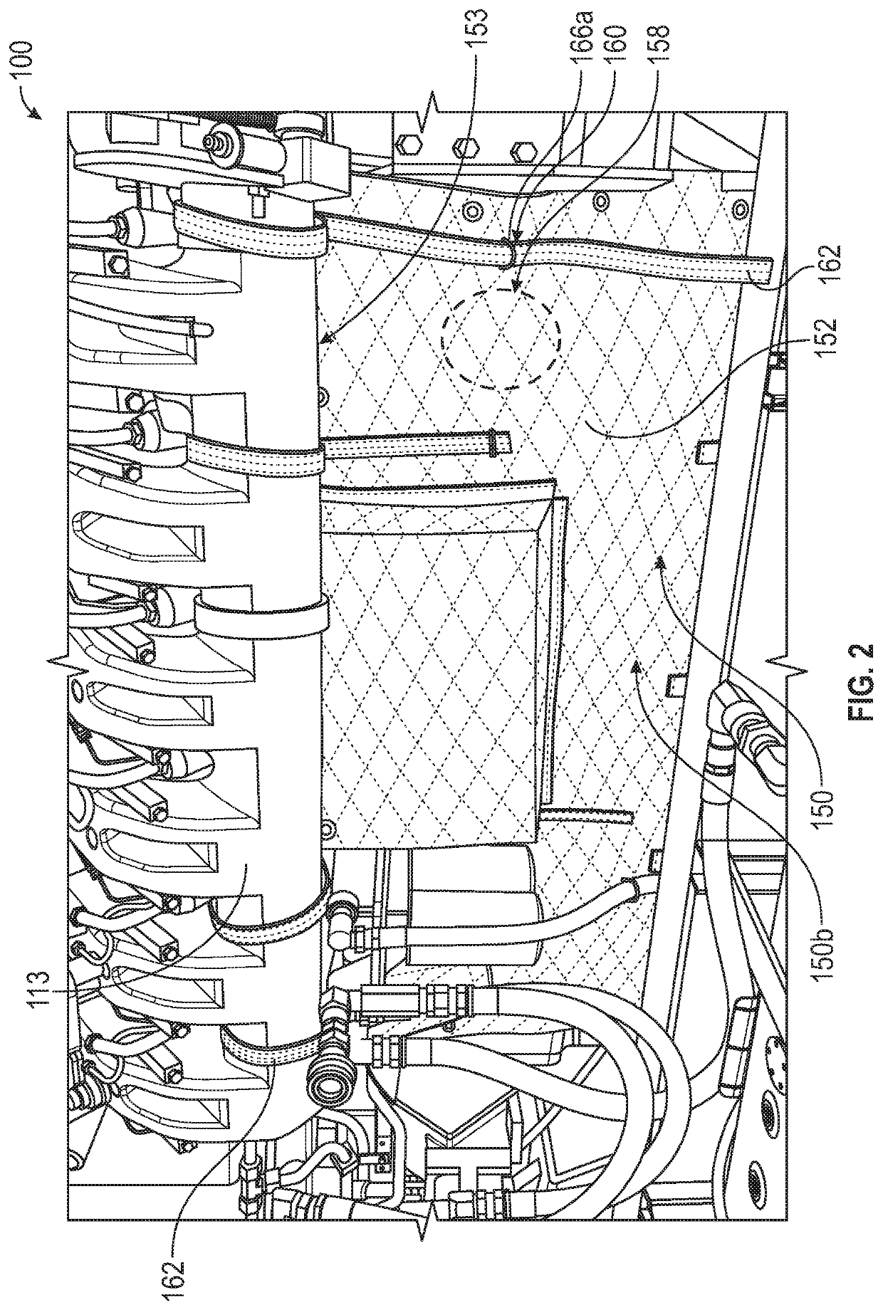
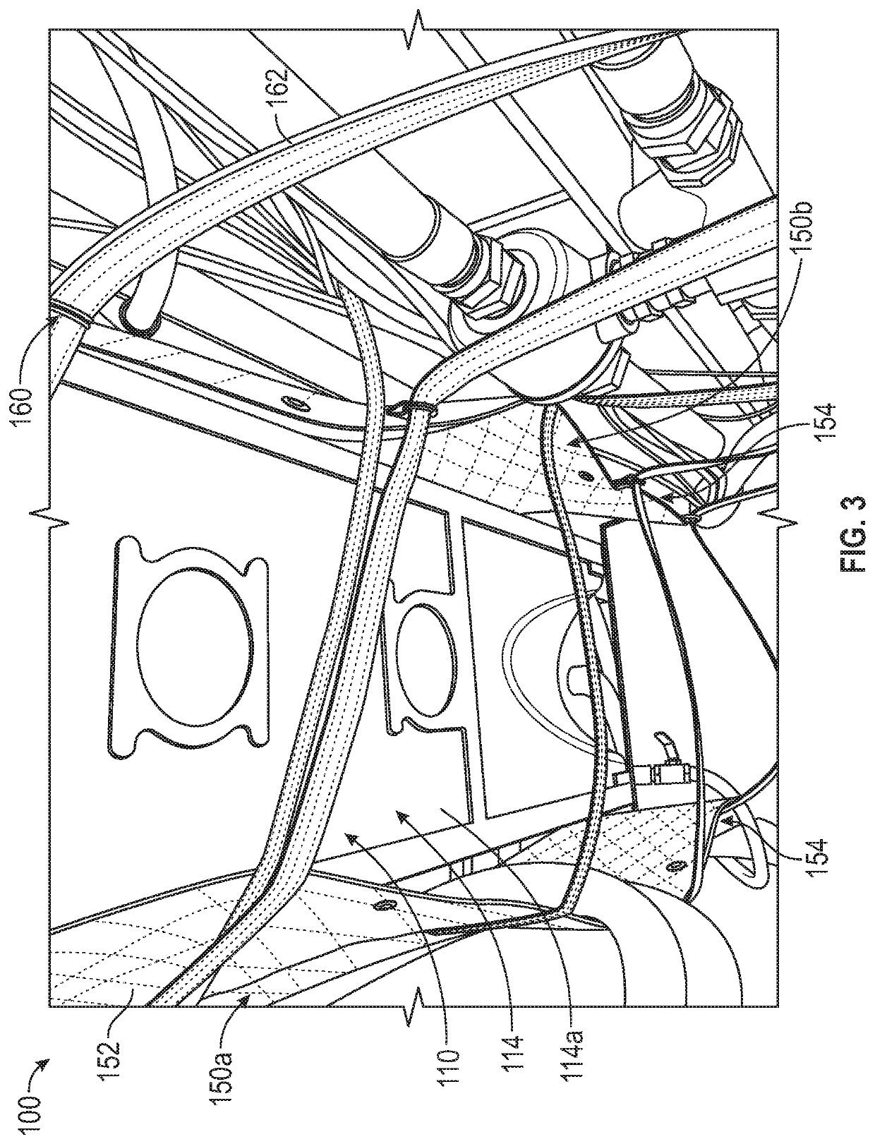
[0023]FIGS. 1 through 4 show an engine system 100, which broadly includes an engine 110 and at least one containment blanket...


PUM


Abstract

An engine system includes an engine having a housing and moving parts for converting energy into mechanical motion; and a first containment blanket having a sheet member and a fastening system. The sheet member extends below a bottom of the engine housing. The fastening system holds the sheet member to the engine such that the first containment blanket laterally shrouds the engine housing to contain debris projected from the engine housing.

Description

CROSS-REFERENCE TO RELATED APPLICATIONS[0001]This application claims priority to U.S. Provisional Patent Application No. 62 / 683,977, filed Jun. 12, 2018, the disclosure of which is incorporated by reference herein in its entirety.BACKGROUND[0002]Hydraulic fracturing operations involve very high pressures and flow rates. Current fleets used in hydraulic fracturing (“fracking”) operations consist of multiples of high pressure pump systems (or “units”) arranged and working together. The individual high-pressure pump systems are interconnected by low-pressure and high-pressure conduits. The low-pressure conduits are used to deliver the frack fluid to the pump systems, and the hydraulic fracturing pump systems energize the frack fluid to a high pressure. The high-pressure conduits aggregate the flow from the multiples of high-pressure pump systems and then deliver an aggregated flow to a well head and ultimately to a formation which is being hydraulically fractured.[0003]Each high-pressu...

Claims


Application Information

Patent Timeline
Patent Type & Authority Applications(United States)
IPC IPC(8): F02B77/10
CPCF02B77/10F02B39/16F02B77/02F02B77/04F02B77/08F02B77/11
Inventor CARRELL, NATHAN EVAN
Owner NEXTIER COMPLETION SOLUTIONS INC
Why Eureka
Try Eureka