Ground-based beamformed communications using mutually synchronized spatially multiplexed feeder links

Active Publication Date: 2020-01-23
VIASAT INC
View PDF0 Cites 21 Cited by
  • Summary
  • Abstract
  • Description
  • Claims
  • Application Information

AI Technical Summary

Benefits of technology

[0005]Among other things, systems and methods are described for providing ground-based beamforming with mutually synchronized, spatially multiplexed gateways in a wireless communications system. Some embodiments operate in the context of a satellite communications system having a number of geographically distributed gateway terminals in communication with a large number of user terminals via a satellite. The satellite can include a focused-beam feeder antenna that communicates with the geographically distributed gateway terminals (e.g., single gateway per beam), and a user antenna that services user terminals in multiple coverage areas with formed user beams. The gateway terminals can communicate forward signals that are beam-weighted and mutually phase-synchronized (e.g.

Problems solved by technology

Some approaches for increasing capacity involve increasing power, but such approaches can have various limitations.
For example, power increases can be limited by power budgets (e.g., practical power limitations of system components, etc.) and/or by regulatory constraints (e.g., maximum allowed transmission power, etc.), and increases in power can have a disproportionately small impact on capacity (e.g., following a logarithmic gain when operating near the Shannon limit).
Decreased beam sizes present a number of challenges, such as increased size, weight, complexity, cost, etc. of the satellite and/or ground terminals; increased accuracy required for antenna pointing and attitude control in the satellite; etc.
Small beam sizes also present challenges with respe

Method used


Image

  • Ground-based beamformed communications using mutually synchronized spatially multiplexed feeder links
  • Ground-based beamformed communications using mutually synchronized spatially multiplexed feeder links
  • Ground-based beamformed communications using mutually synchronized spatially multiplexed feeder links

Examples


Embodiment Construction

[0023]In the following description, numerous specific details are set forth to provide a thorough understanding of the present invention. However, one having ordinary skill in the art should recognize that the invention can be practiced without these specific details. In some instances, circuits, structures, and techniques have not been shown in detail to avoid obscuring the present invention.

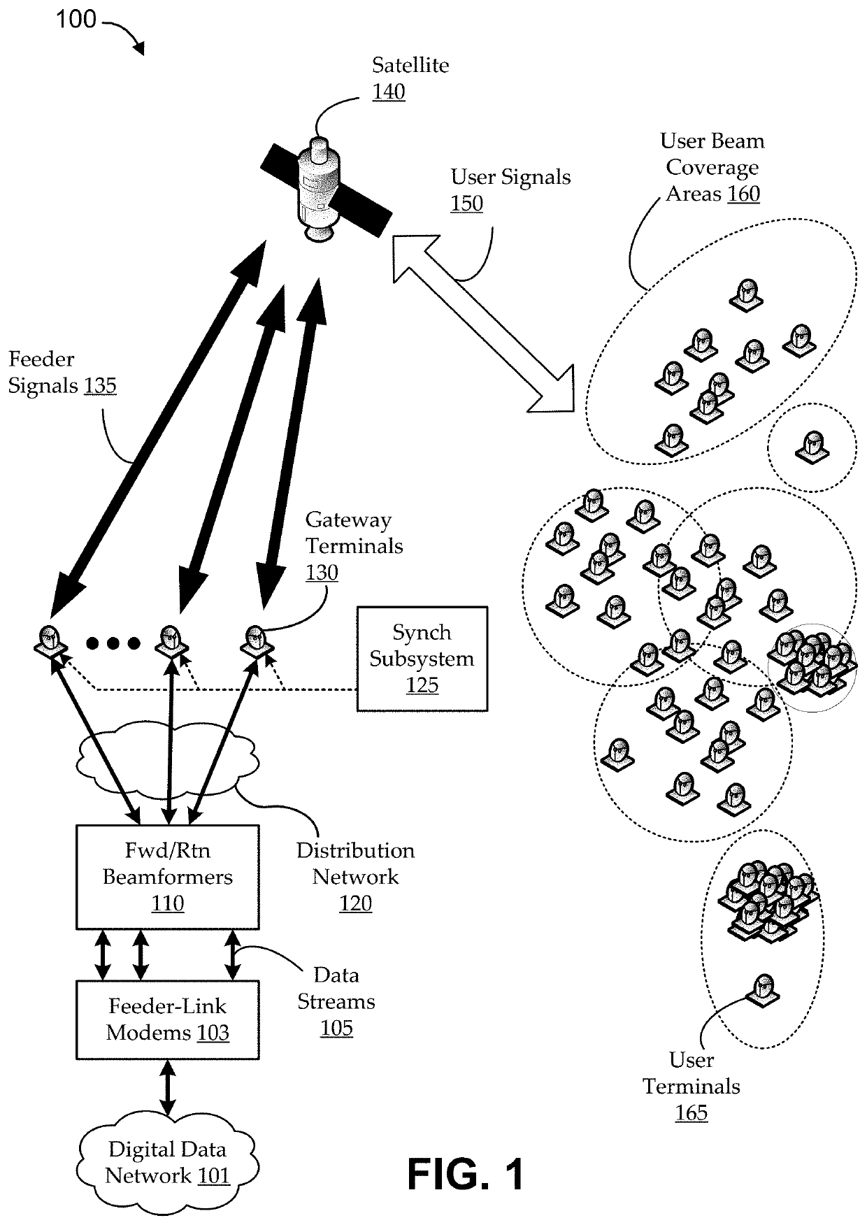
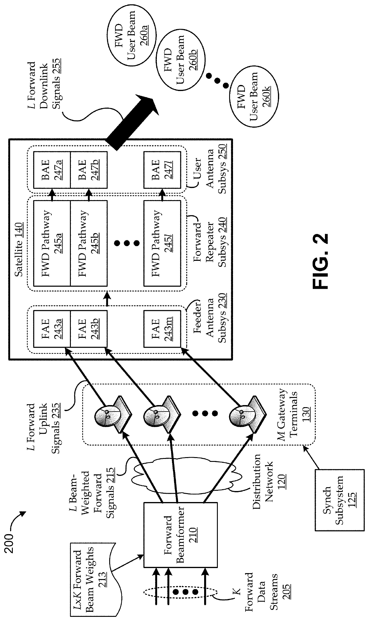
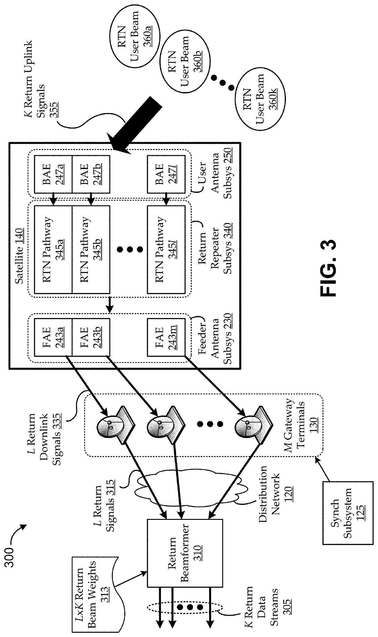
[0024]Embodiments described herein include novel techniques for providing ground-based beamforming with mutually synchronized spatially multiplexed gateways in a wireless communications system (referred to herein as mutually synchronized spatially multiplexed feeder links, or MSSMFL). Some such techniques include mutually phase-synchronizing and beam-weighting spatially multiplexed feeder-link signals in the ground segment of the communications system. For example, in the forward direction, focused feeder beams can be used to receive the mutually phase-synchronized and beam-weighted, spatially ...


PUM


Abstract

Embodiments provide ground-based beamforming with mutually synchronized spatially multiplexed gateways in a wireless communications system. Some embodiments operate in context of a satellite having a focused-beam feeder antenna that communicates with multiple, geographically distributed gateway terminals (e.g., single gateway per beam), and a user antenna that provides communications with user terminals via formed user beams. The gateway terminals can communicate feeder signals that are beam-weighted and mutually phase-synchronized (e.g., according to satellite and/or loopback beacons). For example, the synchronization can enable forward uplink signals to be phase-synchronously received by the satellite, and the beam weighting can enable the forward downlink signals to spatially combine to form forward user beams. Embodiments can achieve extensive bandwidth reuse through mutually synchronized spatial multiplexing of the feeder-link communications.

Description

CROSS-REFERENCE TO RELATED APPLICATIONS[0001]The present application is a continuation of International Application No. PCT / US17 / 57723, filed on Oct. 20, 2017, which claims the benefit of priority to U.S. Provisional Application No. 62 / 411,377, filed on Oct. 21, 2016, the entire contents of each of which are incorporated by reference herein for all purposes.FIELD[0002]Embodiments relate generally to communications systems, and, more particularly, to providing ground-based beamforming with mutually synchronized, spatially multiplexed feeder links.BACKGROUND[0003]In wireless communications systems, such as satellite communication systems, data can be communicated from one location to another via a wireless relay. For example, in a satellite communications system, data can be communicated between gateways and user terminals via a satellite. It is generally desirable to increase capacity of the communications system. Some approaches for increasing capacity involve increasing power, but ...

Claims


Application Information

Patent Timeline
IPC IPC(8): H04B7/185H04B7/06H04B7/026H04B7/204H04B7/212
CPCH04B7/026H04B7/2041H04B7/0617H04B7/18517H04B7/18513H04B7/2125H04B7/18508H04B7/18515Y02D30/70
Inventor BUER, KENNETHPATEROS, CHARLESRALSTON, WILLIAM
Owner VIASAT INC
Why Eureka
Try Eureka