
Energy Absorber Coil for Safety Harness

a technology of energy absorber and safety harness, which is applied in the direction of shock absorbers, safety belts, springs/dampers, etc., can solve the problems of not being able to support the weight of users, affecting the ability of users to move, and the possibility of energy absorbers snagging on objects, etc., to achieve convenient and effective wear of users, improve energy absorber, and improve energy absorber

Active Publication Date: 2020-01-30
MSA TECH
View PDF6 Cites 3 Cited by
  • Summary
  • Abstract
  • Description
  • Claims
  • Application Information

AI Technical Summary

Benefits of technology

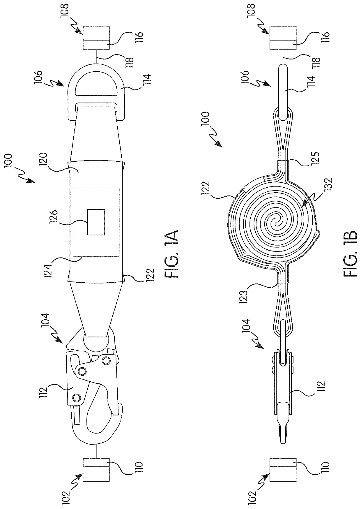
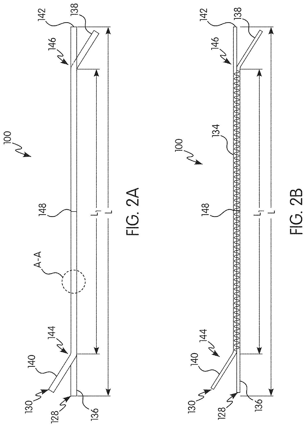
This patent is about an improved energy absorber that can be used with a safety harness. The absorber is designed to be easily and comfortably worn in various work environments, without adding too much weight or restricting movement. It helps to increase safety compliance at the worksite and provide better protection in the event of an fall. The absorber has a reinforced area that prevents separation of the load-bearing webs during deployment. It is made up of a first and second load-bearing webs that form loops at their ends. This design allows for effective energy absorption and minimizes the risk of injury during a fall.

Problems solved by technology

The tear tape webbing is effective at reducing a force that is transmitted to the user during a fall event, but it is not intended to support the weight of the user after the fall event.
One disadvantage of conventional tear tape energy absorbers is that they can compromise the user's ability to move due to their size.
The long overall length of conventional energy absorbers increases a possibility that the energy absorber may snag on an object in the user's work environment.
Another disadvantage is that the tear tape webbing, once deployed, does not support the weight of the user.
Thus, the backup strap must be made of a heavy-duty material that is capable of supporting the weight of the user after the fall event, thereby adding to the cost and weight of the conventional tear tape energy absorber.

Method used


Image

  • Energy Absorber Coil for Safety Harness
  • Energy Absorber Coil for Safety Harness
  • Energy Absorber Coil for Safety Harness

Examples


Embodiment Construction

[0048]As used herein, the singular form of “a”, “an”, and “the” include plural referents unless the context clearly dictates otherwise.

[0049]Spatial or directional terms, such as “left”, “right”, “inner”, “outer”, “above”, “below”, and the like, relate to the invention as shown in the drawing figures and are not to be considered as limiting as the invention can assume various alternative orientations.

[0050]All numbers and ranges used in the specification and claims are to be understood as being modified in all instances by the term “about”. By “about” is meant plus or minus twenty-five percent of the stated value, such as plus or minus ten percent of the stated value. However, this should not be considered as limiting to any analysis of the values under the doctrine of equivalents.

[0051]Unless otherwise indicated, all ranges or ratios disclosed herein are to be understood to encompass the beginning and ending values and any and all subranges or subratios subsumed therein. For exampl...


PUM


Abstract

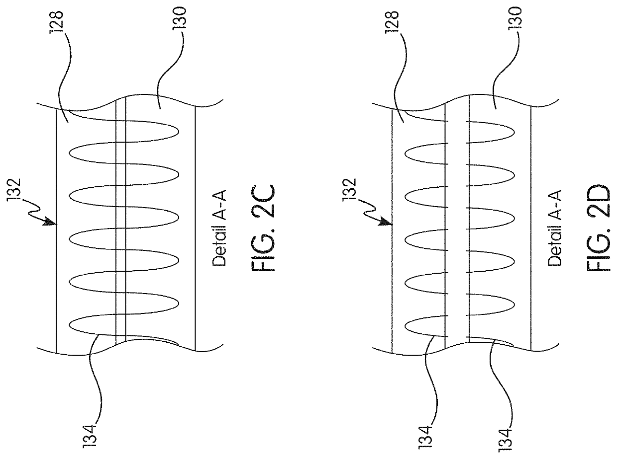
An energy absorber for a safety harness has a first end, a second end, and an energy absorbing portion between the first end and the second end. The energy absorbing portion has a first load-bearing web integrally bound to a second load-bearing web. The energy absorbing portion is coiled in a spiral shape in an undeployed configuration. The energy absorbing portion is deployable from the undeployed configuration to a deployed configuration when the first end is pulled away from the second end due to a force exceeding a minimum predetermined force threshold such that at least a portion of the first load-bearing web tears away from at least a portion of the second load-bearing web. The first load-bearing web and the second load-bearing web are integrally bound in the energy absorbing portion by a plurality of binder threads.

Description

BACKGROUND OF THE INVENTIONField of the Invention[0001]The present invention relates generally to an energy absorber for use with a safety harness and, in particular, to an energy absorber coil for use with a safety harness.Description of the Related Art[0002]As is known in the art, there exist various attachable arrangements to provide assistance to a wearer or ensure the wearer's safety in certain situations. Such attachable arrangements come in many forms, including, but not limited to, harnesses and safety belts. Full body harnesses are widely used as a primary component in a personal fall arrest system. These harnesses can also be used for work positioning, travel restriction, ladder climbing, rescue retrieval, and evacuation. While these harnesses are used mainly in an industrial setting, and particularly the construction industry where the likelihood and danger of falls from heights is both numerous and significant, a full body harness can be used in various other application...

Claims


Application Information

Patent Timeline
Patent Type & Authority Applications(United States)
IPC IPC(8): A62B35/04F16F7/00A62B35/00
CPCA62B35/04F16F7/006A62B35/0075
Inventor BERTOTI, LORYN ASHLEYENRIQUEZ, CARLOS ALBERTO SÁNCHEZKUSHNER, MICHAEL JAMESLOPEZ, LUIS HUMBERTO CARMONAMYERS, GRANT MONNROJAS, DANIEL AGUILAR
Owner MSA TECH
Learn More