Eureka AIR delivers breakthrough ideas for toughest innovation challenges, trusted by R&D personnel around the world.

Surgical tool handle assembly

a surgical tool and handle technology, applied in the field of handles for surgical tools, can solve the problems of wobbling or other movement of the tool, the conventional handle for holding and manipulating surgical tools, and the osteotomes of the knee and other body parts,

Active Publication Date: 2020-02-27
SHUKLA MEDICAL
View PDF0 Cites 1 Cited by
  • Summary
  • Abstract
  • Description
  • Claims
  • Application Information

AI Technical Summary

Benefits of technology

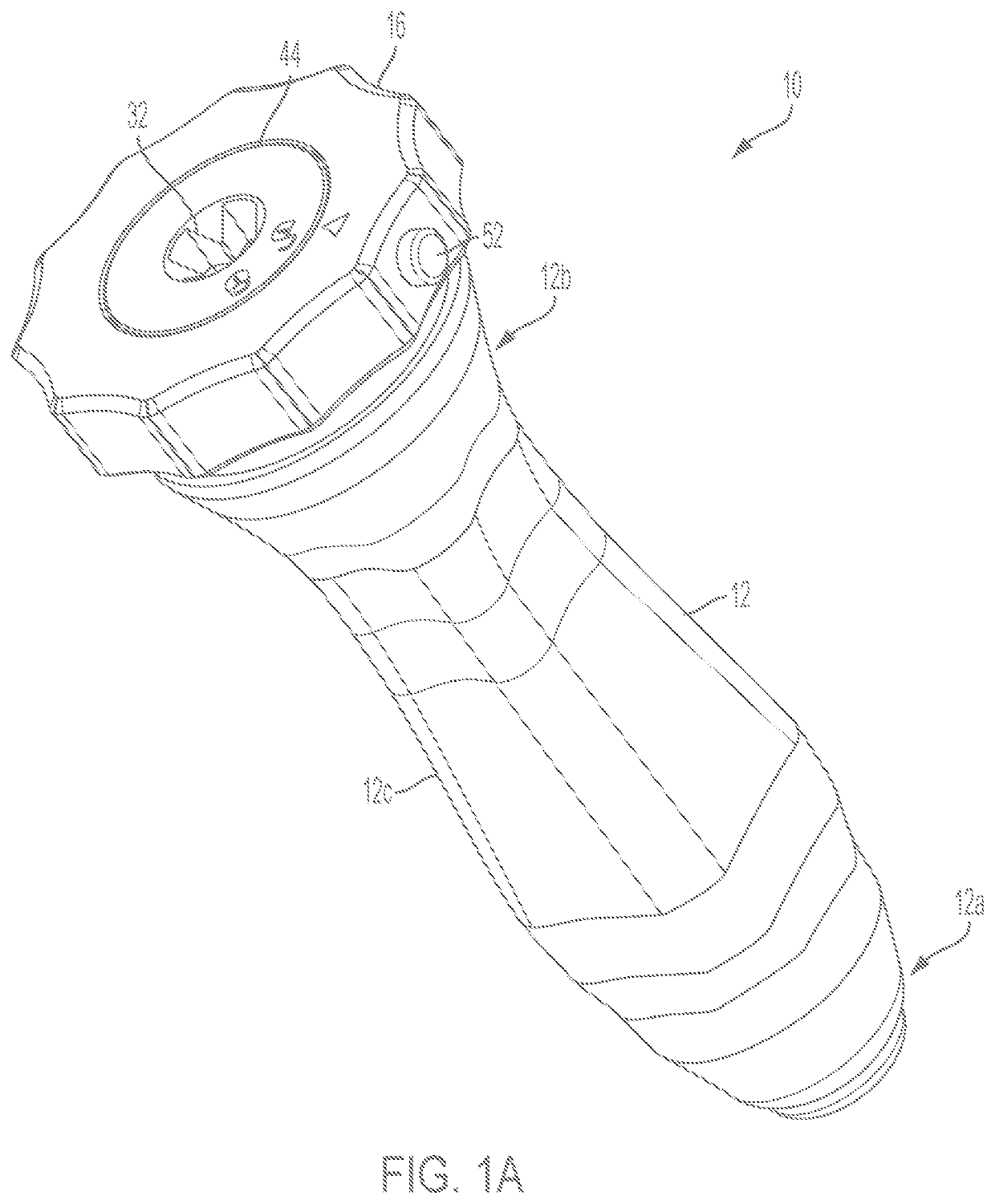
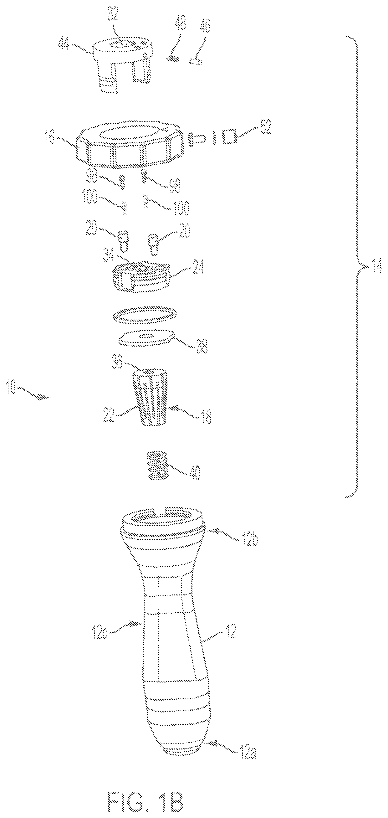
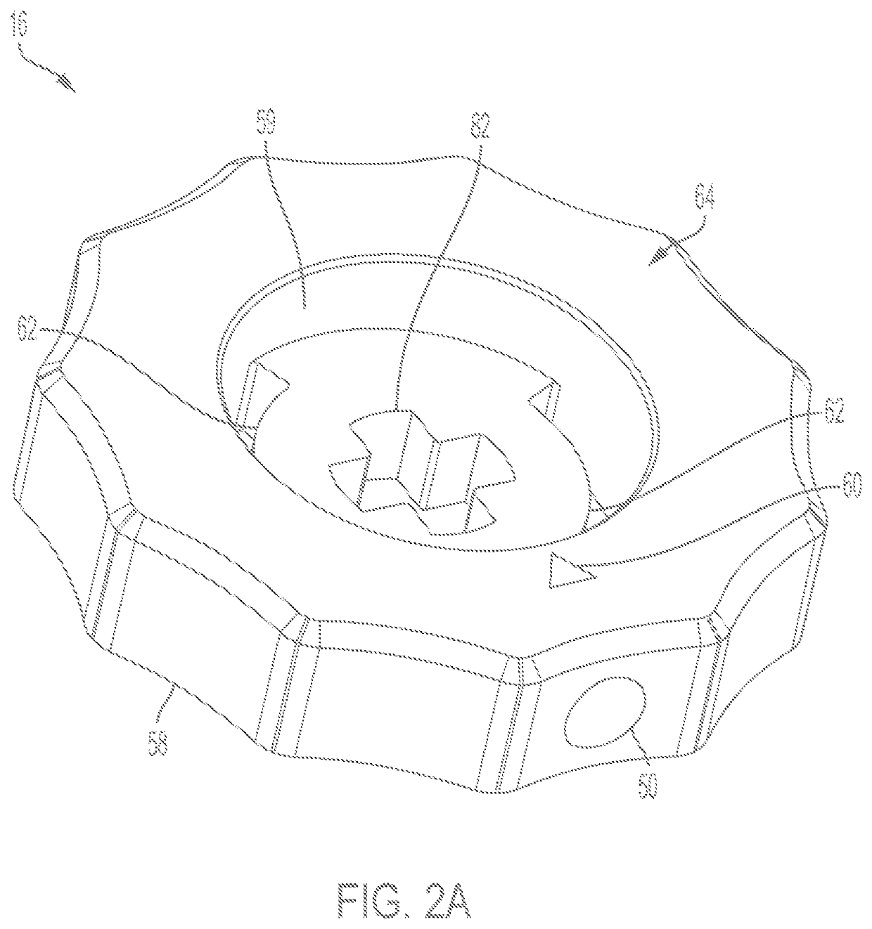
This patent is about a handle assembly for surgical tools. It includes a handle with a locking mechanism attached to it. The locking mechanism includes a locking ring, collet, and a compressible locking pin. The collet is moveable between two positions and is flexible. The locking pin is positioned between the locking ring and collet and includes a deformable locking pin and a retaining ring with a through hole for the locking pin. The handle assembly also includes a tapered receiving cavity and the locking mechanism is positioned within it. The technical effects of this design are improved handling of surgical tools and secure locking of the tools in place.

Problems solved by technology

Conventional handles for holding and manipulating surgical tools, such as osteotomes for the knee and other body parts, do not always provide secure gripping or firm grasping of the surgical tool.
That is, the surgical tool is not rigidly connected to the handle or has too much play relative to the handle, thereby resulting in wobbling or other movement of the tool.
Consequently, such play can adversely affect control or effectiveness of the tool and ultimately the precision of the surgical procedure being performed.

Method used


Image

  • Surgical tool handle assembly
  • Surgical tool handle assembly
  • Surgical tool handle assembly

Examples


Embodiment Construction

[0021]Reference will now be made in detail to the exemplary embodiments of the subject disclosure illustrated in the accompanying drawings. Wherever possible, the same or like reference numbers will be used throughout the drawings to refer to the same or like features. It should be noted that the drawings are in simplified form and are not drawn to precise scale. In reference to the disclosure herein, for purposes of convenience and clarity only, directional terms such as top, bottom, above, below and diagonal, are used with respect to the accompanying drawings. The term “distal” shall mean away from the center of a body. The term “proximal” shall mean closer towards the center of a body and / or away from the “distal” end. With reference to a handle assembly, the “distal end” of the present handle assembly refers to the end of the assembly towards the locking mechanism and the “proximal end” of the present handle assembly refers to the end of the assembly away from the locking mechan...


PUM


Abstract

A handle assembly is disclosed for firmly holding a surgical tool. The handle assembly comprises a handle and a locking mechanism attached to the handle. The locking mechanism includes a locking ring, a collet, and a compressible locking pin engageable with the locking ring and collet. The locking ring is moveable between first and second positions relative to the handle. The first position is an unlocked position whereby the locking pin is in a decompressed state relative to the locking ring and the collet. In the first position, a surgical tool may be inserted and withdrawn from the collet of the locking mechanism. The second position is a locked position whereby the locking pin is in a compressed state relative to the locking ring and the collet. In the second position, a surgical tool is anchored in the collet of the locking mechanism.

Description

CROSS-REFERENCE TO RELATED APPLICATIONS[0001]This application claims the benefit under 35 U.S.C. § 119(e) of U.S. Provisional Application Ser. No. 62 / 722,458, filed Aug. 24, 2018 entitled “Knee Osteotome Handle,” the disclosure of which is hereby incorporated by reference in its entirety for all purposes.BACKGROUND OF THE DISCLOSURE[0002]The present disclosure relates generally to a handle for a surgical tool. Specifically, the present disclosure relates to a handle for releasably receiving a surgical tool such as an osteotome and the like.[0003]An osteotome or similar surgical tool is a chisel-like instrument used to cut or divide bone. Conventional handles for holding and manipulating surgical tools, such as osteotomes for the knee and other body parts, do not always provide secure gripping or firm grasping of the surgical tool. That is, the surgical tool is not rigidly connected to the handle or has too much play relative to the handle, thereby resulting in wobbling or other move...

Claims


Application Information

Patent Timeline
IPC IPC(8): A61B17/16
CPCA61B2017/00473A61B17/1675A61B2017/00469A61B2017/00477A61B2017/00367A61B17/1604A61B2017/0046A61B17/162B23B2231/2005B23B31/20A61B2560/0431A61B17/00A61B17/1613
Inventor SWEITZER, ZACHARY
Owner SHUKLA MEDICAL
Why Eureka
Eureka Blog
Learn More