

Display apparatus
a technology of display apparatus and display screen, which is applied in the direction of identification means, instruments, optical elements, etc., can solve the problems of large reflection from an oblique direction, and achieve the effect of reducing the reflection of external light and improving viewability
- Summary
- Abstract
- Description
- Claims
- Application Information
AI Technical Summary
Benefits of technology
Problems solved by technology
Method used
Image

Examples
first embodiment
1. First Embodiment
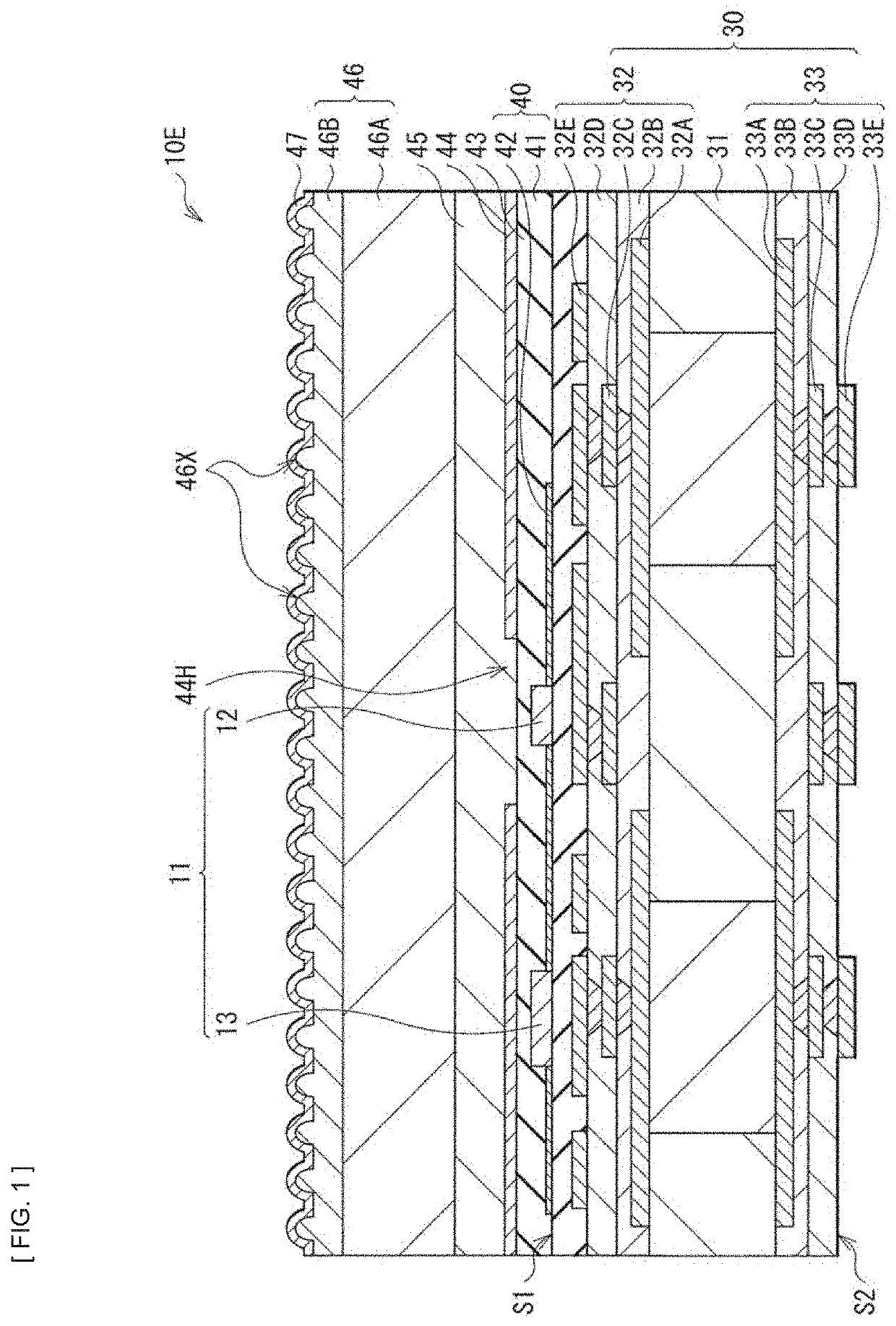
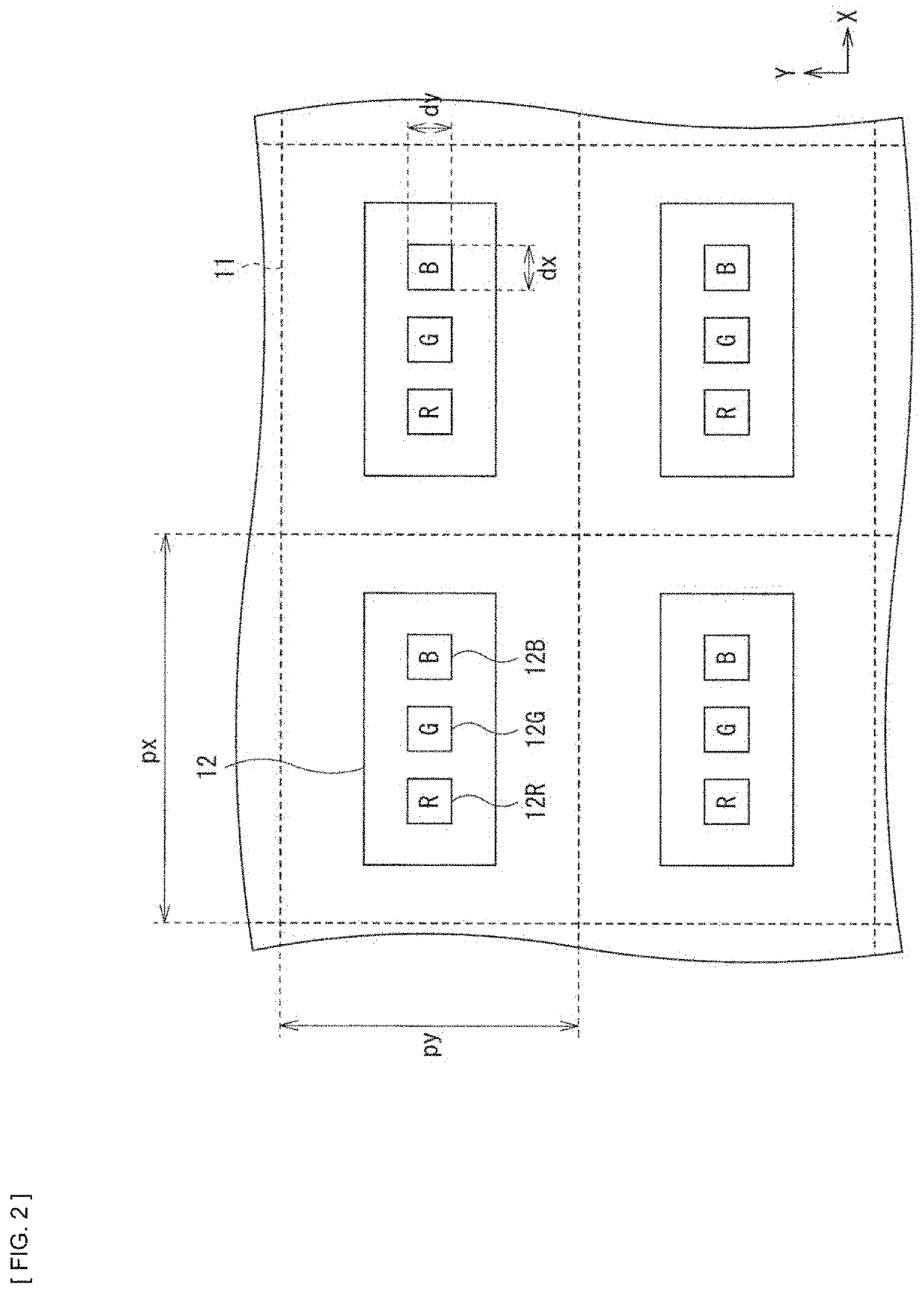
[0035]FIG. 1 illustrates a cross-sectional configuration of a display body device (display body device 10E) according to a first embodiment of the present disclosure. The display body device 10E is used, for example, as a cell included in a so-called tiling display (display apparatus 1; see FIG. 5). As illustrated in FIG. 1, the display body device 10E according to the present embodiment has a configuration in which an optical film 46 having a plurality of projections 46X as irregular structures is bonded to a front surface side (side of a surface S1) of a wiring substrate 30 on which pixels 11 having a plurality of light-emitting elements (e.g., light-emitting elements 12R, 12G, and 12B) as light source elements 12 are arranged. It is to be noted that although FIG. 1 illustrates an example in which one pixel 11 is provided for the sake of simplification of the drawing, actually, for example, a plurality of pixels 11 are arranged in a matrix, for example, as illus...
second embodiment
2. Second Embodiment
[0086]FIG. 11 illustrates a cross-sectional configuration of a display body device (display body device 50E) according to the second embodiment of the present disclosure. The display body device 50E is used, for example, as a cell included in a so-called tiling display (e.g., the display apparatus 1) similarly to the first embodiment. As illustrated in FIG. 11, the display body device 50E has a configuration in which an optical film 56 having a plurality of projections 56X as irregular structures is bonded to the front surface side (side of the surface S1) of the wiring substrate 30 of the wiring substrate on which the pixels 11 having a plurality of light-emitting elements (e.g., the light-emitting elements 12R, 12G, and 12B) are arranged as the light source element 12. In the present embodiment, a tilt angle distribution in a plane (in an X-Y plane) is controlled to cause a percentage of certain angle components within the plurality of projections 56X to be wit...
experiment 1
(Fabrication of Samples)
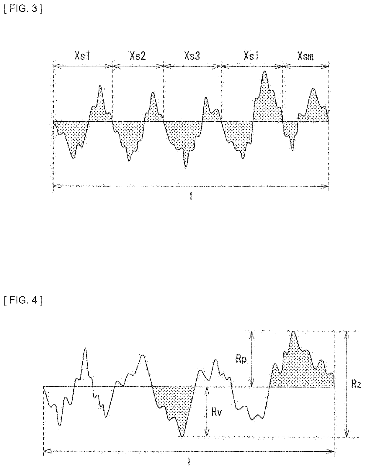
[0102]First, the display body device 10E was prepared in which, the light source elements 12 having three kinds of light-emitting diodes having a mean length of 25 μm as the light-emitting elements 12R, 12G, and 12B were arranged at pitches of 1.26 mm. The optical film 46 having irregular structures (the plurality of projection 46X) on the front surface was bonded onto the display body device 10E (specifically, onto the light-blocking layer 44) to fabricate samples (samples 1 to 6) for evaluation, and color breakup, haze, total light transmittance, and regular reflectance of the samples were measured. The resin layer 46B included in the optical film 46 was roughened by using a coating agent containing a filler. The surface roughness of the resin layer 46B was measured by a laser microscope VK-5000 manufactured by Keyence Corporation. The color breakup, the haze, the total light transmittance, and the regular reflectance were measured with use of the following...
PUM
| Property | Measurement | Unit |
|---|---|---|
| total light transmittance | aaaaa | aaaaa |
| total light transmittance | aaaaa | aaaaa |
| total light transmittance | aaaaa | aaaaa |
Abstract
Description
Claims
Application Information