
Rotary seal arrangement and rotary seal with recirculation function

a technology of rotary seal and recirculation function, which is applied in the direction of engine seals, mechanical equipment, engine components, etc., can solve the problems of undesirable leakage of fluid to be sealed, constant increase of operating pressure, temperature and sliding speed of rotary seals, and inability to ensure the recirculation function of rotary seals, so as to improve the lubricating behavior of the dynamic contact surface area of the sealing lip and the sealing surface of the second machine element, the effect of lub

Active Publication Date: 2020-03-12
TRELLEBORG SEALING SOLUTIONS GERMANY
View PDF3 Cites 1 Cited by
  • Summary
  • Abstract
  • Description
  • Claims
  • Application Information

AI Technical Summary

Benefits of technology

The invention is about a new rotary seal arrangement that reduces friction and wear during operation. Instead of putting the sealing lip structures that are essential for recirculation capacity on the front side of the sealing lip, which is subject to wear, they are placed in regions of the sealing lip that are far from the sealing surface of the second machine element. This eliminates direct mechanical contact and wear-prone tribo structures to ensure better sealing performance and longer lifespan of the rotary seal arrangement. The rotary seal and other additional attachments can be packaged into a cartridge for easier installation and maintenance.

Problems solved by technology

Such rotary seals are in practice exposed to continually increasing operating pressures, temperatures and sliding speeds, not least due to the technical advancement of the units.
The failure of rotary seals results in an undesirable leakage of the fluid to be sealed, which may have devastating consequences, in particular, in critical applications.
These tribo structures are inevitably subject to wear in operational use of the rotary seal arrangement in operational use, so that the recirculation function of the rotary seal often may not be guaranteed even after a short period of use of the rotary seal.
The life of the rotary seal can thereby be shortened unnecessarily.

Method used


Image

  • Rotary seal arrangement and rotary seal with recirculation function
  • Rotary seal arrangement and rotary seal with recirculation function
  • Rotary seal arrangement and rotary seal with recirculation function

Examples


Embodiment Construction

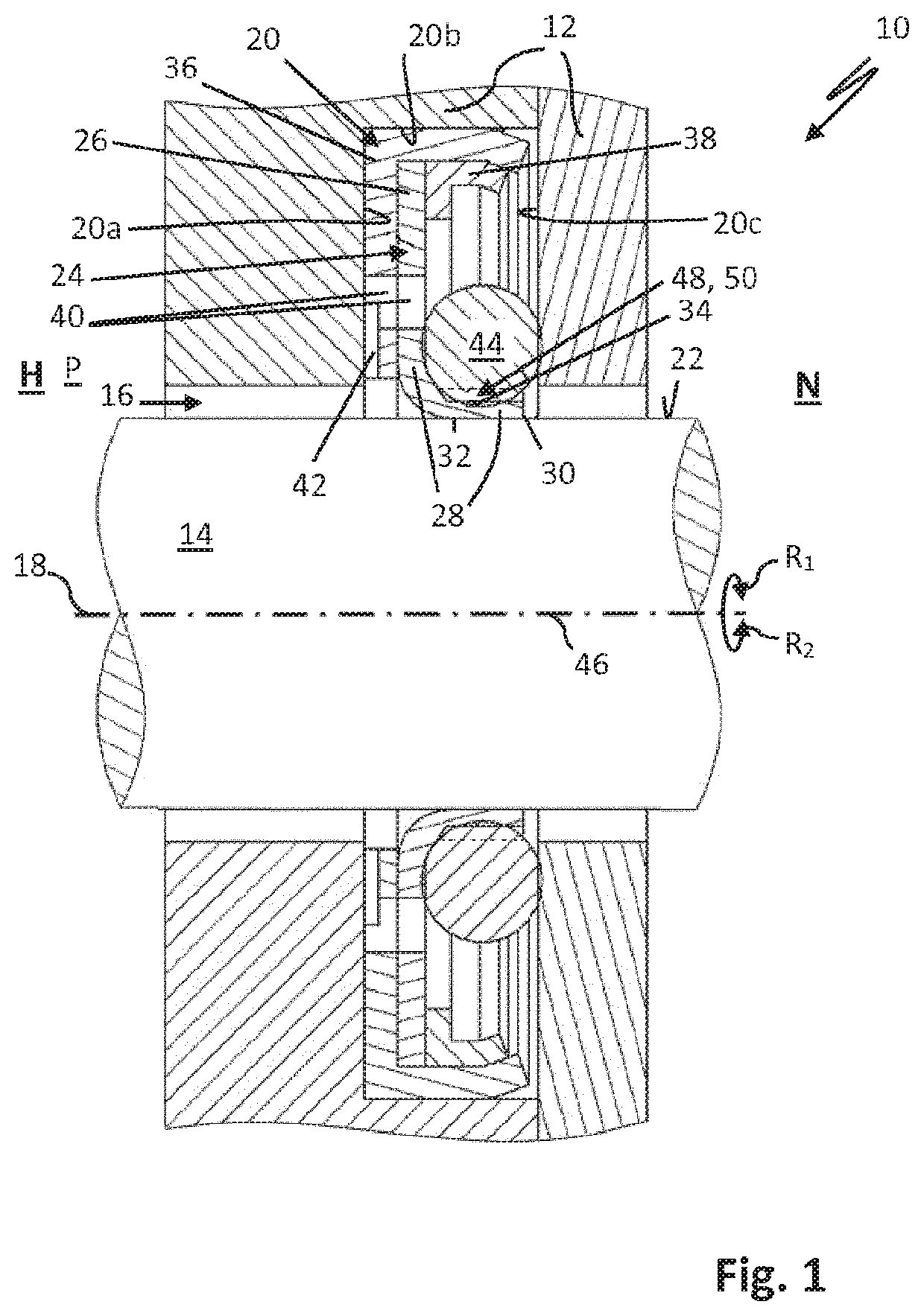
[0052]FIG. 1 shows a rotary seal arrangement 10 having a first and a second machine element 12, 14 spaced apart to form a sealing gap 16 and arranged rotatably about a rotational axis 18 in opposite directions of rotation R1, R2 relative to each other. The first machine element 12 has a seal-holding structure, here a holding groove 20 with a high-pressure side groove flank 20a, a groove bottom 20b and a low-pressure side groove flank 20c. The second machine element 14 comprises a dynamic sealing surface 22. A rotary seal 24 serves to seal a high-pressure side H of the seal gap 16 which is pressurizable with a fluid against a low-pressure side N of the seal gap. The rotary seal 24 is designed here as a so-called radial shaft seal. The rotary seal 24 may be made in one piece and comprises a holding section 26 arranged substantially radially and a sealing lip 28 with a sealing edge 30 which extends in the axial direction from the holding section 26, here in the direction of the low-pre...


PUM


Abstract

A rotary seal assembly has a first and second machine element spaced apart forming a sealing gap. The first machine element has a seal-holding structure and the second machine element a sealing surface. A rotary seal is held on the seal-holding structure of the first machine element which has a sealing lip, the front side of which faces the sealing surface and at least partially abuts the sealing surface of the second machine element, pretensioned in a dynamically sealing manner. The sealing lip has pockets on its rear side or on its end face facing the high pressure side. The sealing lip on its rear side, in the case of rearwardly arranged pockets, is tensioned against the sealing surface by an elastically deformable pretensioning ring, and is tensioned in the case of the front side pockets by an elastic resilience inherent in the material of the rotary seal.

Description

CROSS-REFERENCE TO RELATED APPLICATIONS[0001]This continuation application claims priority to PCT / EP2018 / 063092 filed on May 18, 2018 which has published as WO 2018 / 211073 A1 and also the German application number 10 2017 208 574.6 filed on May 19, 2017, the entire contents of which are fully incorporated herein with these references.DESCRIPTIONField of the Invention[0002]The invention relates to a rotary seal arrangement and a rotary seal with recirculation function. The rotary seal arrangement comprises a first and a second machine element, which are spaced apart from one another while forming a sealing gap and are arranged so as to be movable relative to one another about an axis of rotation. The first machine element has a seal-holding structure and the second machine element has a sealing surface. A rotary seal serves to seal a high-pressure side H of the seal gap pressurizable with a fluid against a low-pressure side N of the seal gap. The rotary seal is arranged held on the s...

Claims


Application Information

Patent Timeline
Patent Type & Authority Applications(United States)
IPC IPC(8): F16J15/16F16J15/3244F16J15/3208F16J15/3236F16J15/34
CPCF16J15/164F16J15/344F16J15/3236F16J15/3208F16J15/3244F16J15/3228F16J15/3448
Inventor WEHMANN, CHRISTOPHFRANZ, MARTIN
Owner TRELLEBORG SEALING SOLUTIONS GERMANY
Learn More