Eureka AIR delivers breakthrough ideas for toughest innovation challenges, trusted by R&D personnel around the world.

Circumferential lock mechanism, battery locking device, power battery pack and vehicle

Active Publication Date: 2020-03-26
NIO ANHUI HLDG CO LTD
View PDF0 Cites 2 Cited by
  • Summary
  • Abstract
  • Description
  • Claims
  • Application Information

AI Technical Summary

Benefits of technology

The patent is about a new way to lock a battery pack in place in a vehicle. The new mechanism uses a tapered surface and pins to complete continuous locking. This solution is simple and reliable. The technical effect of this innovation is better battery security and protection in a vehicle.

Problems solved by technology

For example, how to ensure a constant pre-tightening force in a threaded connection is a difficult problem in the industry.
The structures can provide only limited graduated locking and positioning.
With these techniques, an engagement angle of the threaded member is uncertain when a threading torque reaches a predetermined value.
If teeth or grooves cannot be engaged at a corresponding angle, the threaded member is still susceptible to loosening, and constant threading torque cannot be kept.
The structures in these techniques also can provide only limited graduated locking and positioning.
Although, continuous locking and positioning can be achieved theoretically by arranging as many graduated locking and positioning parts as possible, it is impossible to achieve the true continuous locking and positioning by doing so.
However, there are still disadvantages that continuous locking and positioning cannot be implemented and constant threading torque cannot be kept.

Method used


Image

  • Circumferential lock mechanism, battery locking device, power battery pack and vehicle
  • Circumferential lock mechanism, battery locking device, power battery pack and vehicle

Examples


Embodiment Construction

[0037]Specific embodiments of the invention are described below in detail with reference to the accompanying drawings. In the accompanying drawings, the same reference numerals represent the same or corresponding technical features.

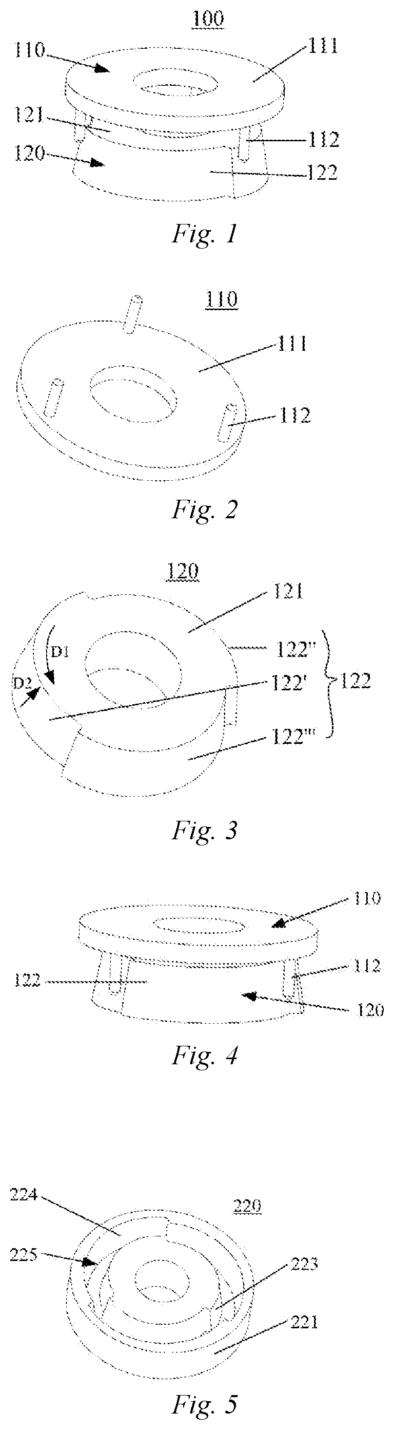
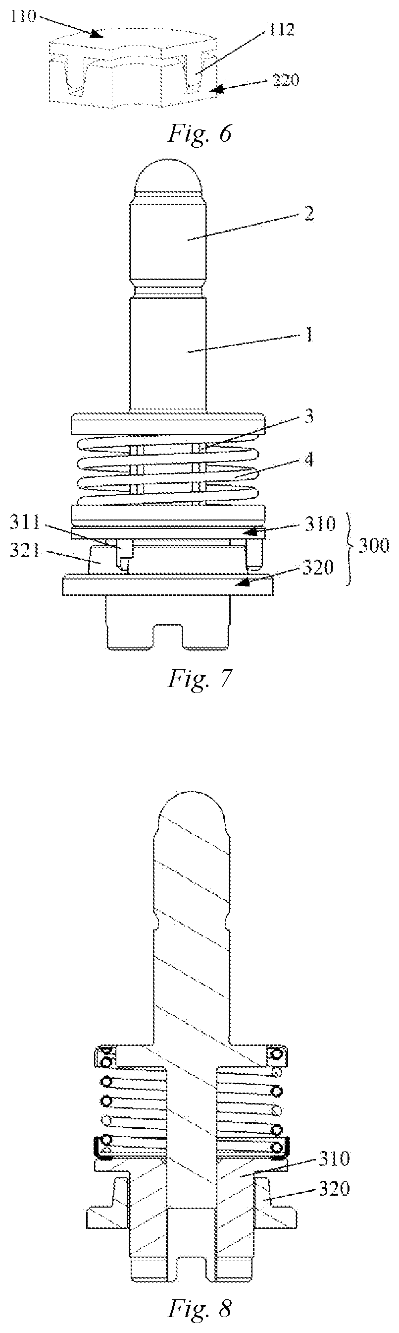
[0038]FIG. 1 is a schematic diagram of an embodiment of a circumferential locking mechanism according to the invention. As can be seen from the figure, the circumferential locking mechanism 100 comprises a first component 110 and a second component 120. When the first component 110 is engaged with the second component 120, pins 112 on the first component 110 abut against a limiting face 122 on the second component 120, so as to restrict the relative circumferential rotation between the first component 110 and the second component 120. It should be understood that a person skilled in the art appreciates that any force-applying device such as a spring may be used to impel the first component to engage with the second component. Accordingly, a third componen...


PUM


Abstract

A circumferential locking mechanism, a battery securing device comprising same, a battery pack, and a vehicle are provided. The circumferential locking mechanism (100) comprises: a first component (110), the first component (110) comprising a first body (111) and pins (112) extending from the first body (111) in an axial direction, the pins (112) being distributed on the first body (111) along a first circumference; a second component (120), the second component (120) comprising a second body (121) and a limiting face (122) on the second body (121), the limiting face (122) extending in a circumferential direction and comprising segments, the radius of the limiting face (122) tapering in both the axial and circumferential directions at the segments; and a third component for impelling the first component (110) to engage with the second component (120), wherein the first component (110) and the second component (120) are arranged such that the first circumference and the limiting face (122) are coaxial, and when the first component (110) is engaged with the second component (120), the pins (112) abut against the limiting face (122). The pins (112) can be fitted to the limiting face (122) by means of the foregoing structure to complete continuous locking.

Description

TECHNICAL FIELD[0001]The invention relates to the technical field of circumferential anti-loosening and locking of components, and particularly to a circumferential locking mechanism.[0002]Further, the invention further relates to a vehicle, a battery pack, and a battery securing device comprising the circumferential locking mechanism.BACKGROUND ART[0003]It is often experienced that relatively rotating between two components needs to be restricted.[0004]For example, how to ensure a constant pre-tightening force in a threaded connection is a difficult problem in the industry. Currently, common anti-loosening structures include a movable threaded member provided with a multi-tooth anti-loosening structure, a groove-shaped anti-loosening structure, or the like. The structures can provide only limited graduated locking and positioning. With these techniques, an engagement angle of the threaded member is uncertain when a threading torque reaches a predetermined value. If teeth or grooves...

Claims


Application Information

Patent Timeline
IPC IPC(8): B60K1/04H01M2/10H01M50/262
CPCB60L53/80B60S5/06H01M2/1083B60K2001/0455H01M2220/20B60K1/04B60L50/66F16B1/00F16B19/02H01M50/262F16B2200/99Y02E60/10B60K1/00
Inventor BENGTSSON, JANLI, NANDING, XIKUNTIAN, XIAOTAO
Owner NIO ANHUI HLDG CO LTD
Why Eureka
Eureka Blog
Learn More