Microscope apparatus

a microscope and apparatus technology, applied in the field of microscope apparatus, can solve problems such as difficulty in accurately capturing light, and achieve the effect of accurately capturing weak light and suppressing the influence of heat on the sampl

Active Publication Date: 2020-04-02
SYSMEX CORP
View PDF0 Cites 0 Cited by
  • Summary
  • Abstract
  • Description
  • Claims
  • Application Information

AI Technical Summary

Benefits of technology

[0031]It is possible to reliably suppress the entry of external light into the sample setting unit, accurately capture weak light, and suppress the influence of heat on the sample. A clear image also can be captured when imaging is performed by light from above.

Problems solved by technology

Therefore, a problem arises inasmuch as it is difficult to accurately capture light when detecting and capturing a weak light.

Method used


Image

  • Microscope apparatus
  • Microscope apparatus
  • Microscope apparatus

Examples


first modification

Microscope Apparatus Structure of a First Modification)

[0130]Next, the configuration of the microscope apparatus 400 according to a first modification will be described with reference to FIGS. 19A and 19B.

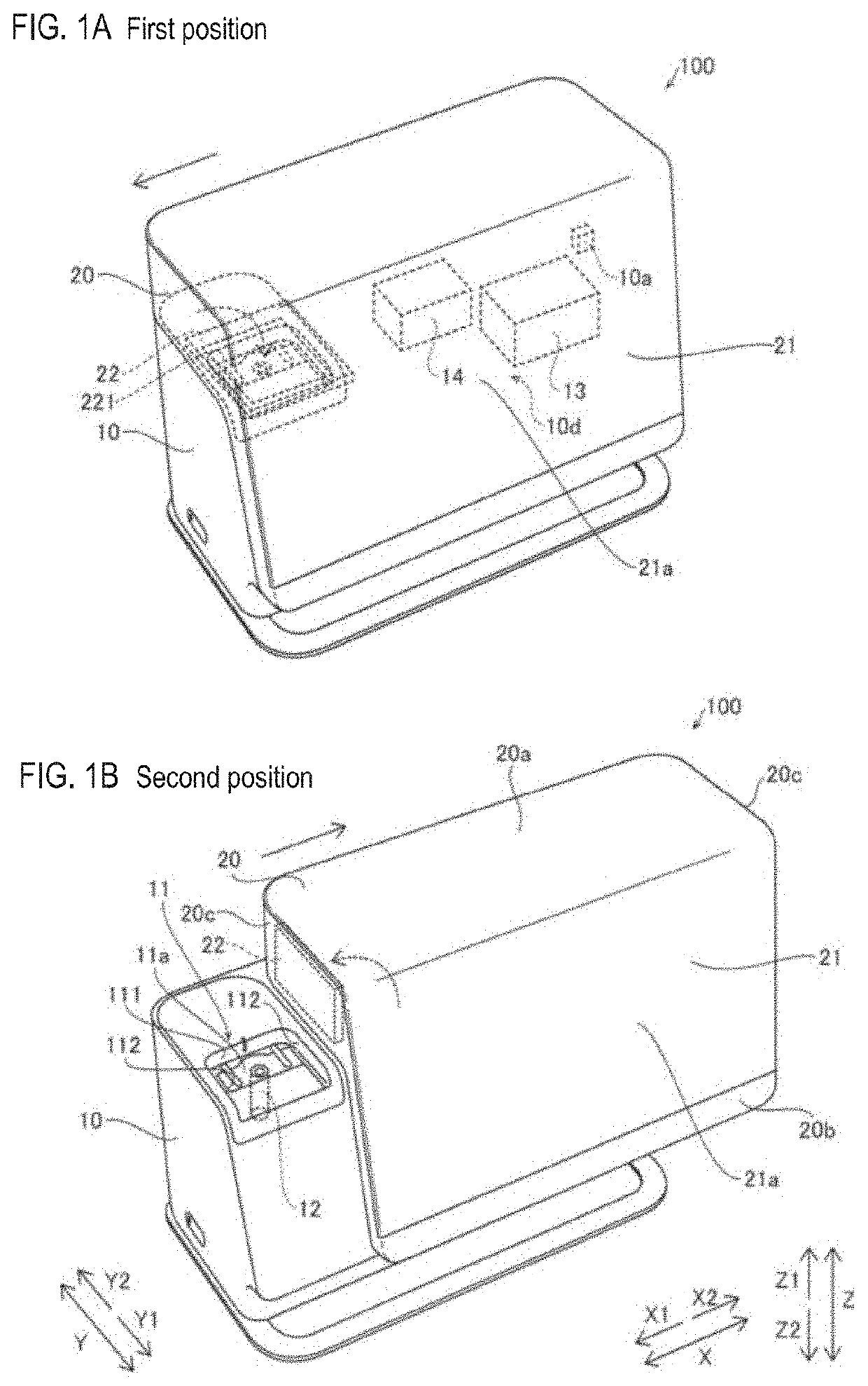
[0131]As shown in FIGS. 19A and 19B, the microscope apparatus 400 includes a housing unit 410 and a first cover 420. The housing unit 410 is provided with a sample setting unit 411. A display unit 421 is integrally provided on the first cover 420. The sample setting unit 411 is provided with a second cover 22 that covers the sample setting unit 411. As shown in FIG. 19B, the first cover 420 is disposed on the front surface side (Y1 direction side) of the housing unit 410. The first cover 420 has a flat plate shape extending along a plane (XZ plane) perpendicular to the installation surface of the housing unit 410.

[0132]The first cover 420 is configured to be movable between a first position (light shielding position) and a second position (open position) by sliding along the vertic...

second modification

Microscope Apparatus Structure of Second Modification

[0133]Next, with reference to FIGS. 20A and 20B, the structure of the microscope apparatus 500 of a second modification is described.

[0134]As shown in FIGS. 20A and 20B, the microscope apparatus 500 includes a housing unit 510 and a first cover 520. The housing unit 510 is provided with a sample setting unit 511. The first cover 520 is integrally provided with a display unit 521. The sample setting unit 511 is provided with a second cover 22 that covers the sample setting unit 511. As shown in FIG. 20B, the first cover 520 is disposed on the front surface side (Y1 direction side) of the housing unit 510. The first cover 520 has a flat plate shape extending along a plane (XZ plane) perpendicular to the installation surface of the housing unit 510.

[0135]The first cover 520 is configured to be movable between a first position (light-shielding position) and a second position (open position) by sliding along the horizontal direction (X...

third modification

Microscope Apparatus Structure of Third Modification

[0136]Next, with reference to FIGS. 21A and 21B, and FIG. 22, the structure of the microscope apparatus 600 of a third modification is described.

[0137]As shown in FIG. 21B, the microscope apparatus 600 includes a housing unit 610 and a first cover 620. The housing unit 610 is provided with a sample setting unit 611. A display unit 621 is integrally provided on the first cover 620. The sample setting unit 611 is provided with a second cover 22 that covers the sample setting unit 611. As shown in FIGS. 21A and 21B, the first cover 620 is disposed on the front surface side (Y1 direction side) of the housing unit 610. The first cover 620 has a flat plate shape that extends along a plane (XZ plane) perpendicular to the installation surface of the housing unit 610.

[0138]The first cover 620 is configured to be movable between a first position (light shielding position) and a second position (open position) by sliding along the horizontal ...


PUM

PropertyMeasurementUnit
fluorescenceaaaaaaaaaa
fluorescentaaaaaaaaaa
fluorescent imagesaaaaaaaaaa

Abstract

A microscope apparatus includes: a sample setting unit in which a sample is set; an imaging unit configured to image the sample set in the sample setting unit; a housing unit on which the sample setting unit is arranged, and which is configured to internally accommodate the imaging unit; a first light source configured to irradiate light for fluorescence excitation on the sample in the sample setting unit; a first cover configured to be movable to a first position that covers the sample setting unit and a second position that opens the sample setting unit; and a second cover configured to be movable within the first cover; and a second light source arranged in a space covered with the second cover and configured to irradiate light on the sample in the sample setting unit.

Description

CROSS REFERENCE TO RELATED APPLICATIONS[0001]This application claims priority from prior Japanese Patent Application No. 2018-184825, filed on Sep. 28, 2018, entitled “MICROSCOPE APPARATUS”, the entire contents of which are incorporated herein by reference.FIELD OF THE INVENTION[0002]The present invention relates to a microscope apparatus.BACKGROUND[0003]Japanese Patent Publication No. 2006-162764, as shown in FIG. 28, discloses a microscope apparatus 800 including a stage 801 for placing a sample, a camera 802 for imaging a sample placed on the stage 801, a light source 803 for irradiating transmission light for bright field observation toward the stage 801, and a light source 804 for irradiating light for fluorescence observation toward a stage 801. In the microscope apparatus 800, the front of the stage 801 is covered with a removable sample cover 805, and the upper portion of the stage 801 is covered with an openable / closable lid 806, so that external light is prevented from ent...

Claims


Application Information

Patent Timeline
Patent Type & Authority Applications(United States)
IPC IPC(8): G01N21/64G02B21/00G02B21/36G02B21/26
CPCG02B21/26G01N21/6458G02B21/0032G02B21/361G02B21/368G02B21/06G02B21/24G02B21/16G02B21/362G02B21/0088G02B21/088G02B21/14G02B21/0076G02B21/12
Inventor OKADA, MASAYAIWANAGA, SHIGEKI
Owner SYSMEX CORP
Why Eureka
Try Eureka