Bus packet format displaying method for logic analyzer

a logic analyzer and bus packet technology, applied in error detection/correction, database management systems, instruments, etc., can solve the problems of users not being able to easily observe and analyze variables, and not being able to display packet data in the standard specifications of the bus, so as to facilitate the user to determine the correctness of the packet, enhancing the efficiency of development and debugging

Active Publication Date: 2020-04-09
ZEROPLUS TECH CO LTD
View PDF0 Cites 2 Cited by
  • Summary
  • Abstract
  • Description
  • Claims
  • Application Information

AI Technical Summary

Benefits of technology

The present invention allows the user to easily understand the meaning and value of the second packet section that does not meet the specification format of the bus standard. This helps the user determine whether the packets are correct, which improves the efficiency of development and debugging.

Problems solved by technology

However, bus data that are not in the standard specifications of the bus are often the focus of attention.
However, since these variables are not in the bus standard specifications, the conventional logic analyzer will not know the meaning of the variables, and therefore the meaning of each of the variables will not be correspondingly displayed on the operation screen.
As a result, users cannot easily observe and analyze these variables during development and debugging.

Method used


Image

  • Bus packet format displaying method for logic analyzer
  • Bus packet format displaying method for logic analyzer
  • Bus packet format displaying method for logic analyzer

Examples


first embodiment

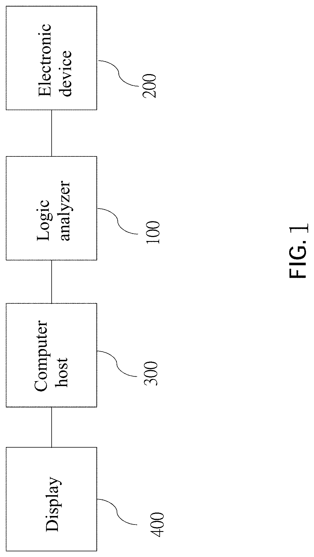
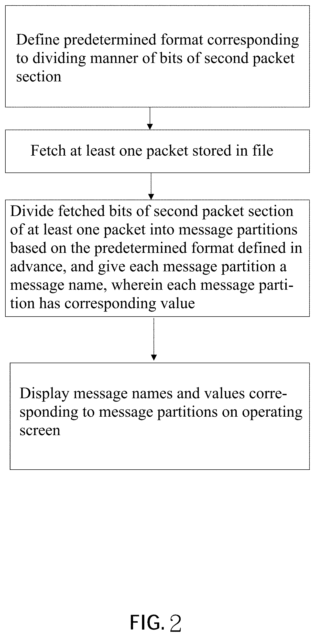
[0020]FIG. 1 shows a structure of a logic analyzer 100 according to the present invention and is adapted to illustrate a flowchart of a packet displaying method shown in FIG. 2.

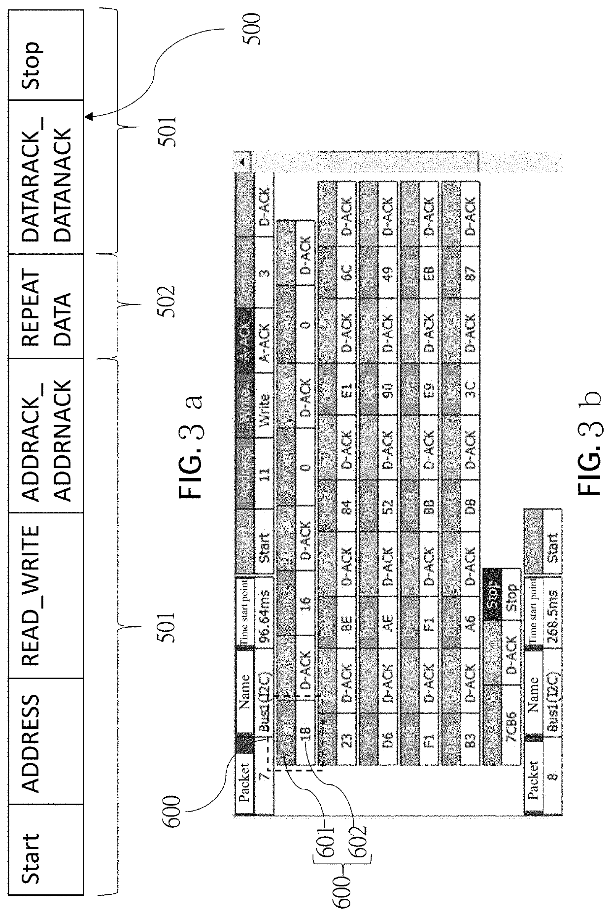
[0021]The logic analyzer 100 is electrically connected to an electronic device 200 to fetch a plurality of packets 500 of a bus of the electronic device 200 and is further electrically connected to a computer host 300 to merge the plurality of packets into a file and to store the file in the computer host 300. The computer host 300 executes a decoding program to retrieve the file and analyzes the plurality of packets according to a predetermined format defined in advance, and then an analysis result would be displayed on an operating screen through a display 400. In order to illustrate easily, one of the packets 500 shown in FIG. 3a is used for illustration. In the current embodiment, the predetermined format includes a data format table 800, a major index description table 700, and a string table 900 shown i...

second embodiment

[0036]In the second embodiment, as shown in FIG. 7, the data format table 800 has the same two of the major index variables 812, and therefore, the two corresponding minor index variables 838 are used to assist the computer host 300 to determine the major index variable 812 to be selected, wherein the two message name strings 814 corresponds to the two minor index variables 838 for being used as the name of the two major index variables 812.

[0037]In the second embodiment, as shown in FIG. 8, a name of the major index 722 is formed by linking the two packet section names 712 of the first packet sections 501 with the “+” sign and filling in the major index field 722a.

[0038]As shown in FIG. 7 and FIG. 8, the computer host 300 fetches a plurality of fetching bits of the first packet sections 501 within the bit fetching range based on the bit fetching range and compares the major index variables 812 of the data format table 800 to find the major index variable 812 that matches the fetch...


PUM


Abstract

A bus packet format displaying method for a logic analyzer is disclosed. The logic analyzer fetches at least one packet of a bus of an electronic device. A computer host divides a plurality of bits of a second packet section of the packet into a plurality of message partitions according to a predetermined format defined in advance. Each of the message partitions has a value. The computer host gives a message name to each of the message partitions corresponding to the values and displays the message names and the values fetched by the logic analyzer on an operating screen.

Description

BACKGROUND OF THE INVENTIONTechnical Field[0001]The present invention is related to a packet data analysis method, and more particularly to a bus packet format displaying method for a logic analyzer.Description of Related Art[0002]It is known that in addition to the well-defined standard specifications, there are still bus data that are not in the standard format specifications. However, bus data that are not in the standard specifications of the bus are often the focus of attention. Therefore, a conventional logic analyzer displays the bus data not in the standard specifications of the bus on an operation screen, so that the user can observe the variables of such bus data.[0003]However, since these variables are not in the bus standard specifications, the conventional logic analyzer will not know the meaning of the variables, and therefore the meaning of each of the variables will not be correspondingly displayed on the operation screen. As a result, users cannot easily observe and...

Claims


Application Information

Patent Timeline
IPC IPC(8): H04L29/06G06F16/25G06F16/22
CPCH04L69/22G06F16/258G06F16/2282H04L67/75H04L41/22G06F11/364G01R31/3177G06F11/25
Inventor LIN, SUNG-HUI
Owner ZEROPLUS TECH CO LTD
Why Eureka
Try Eureka